










November 2026 | For C&I asset owners, EPCs, and technical due-diligence teams
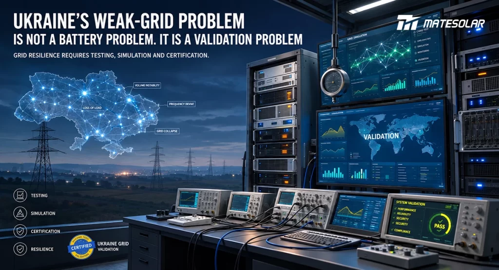
Here is the uncomfortable truth about Ukraine’s commercial and industrial storage market in late 2026: the regulatory door has swung open wider than at any point since the war began, and yet the technical bar for actually operating a storage system as a resilience asset has never been higher.
SolarPower Europe put the market’s first principle in plain language in August. Quoting Vladyslav Sokolovskyi of the Solar Energy Association of Ukraine, the report said batteries in Ukraine “are more than an energy technology, they are a resilience technology.” And then the line that separates Ukraine from every other European storage market: small and medium-sized businesses install these systems for one reason—“energy security first, economics second”.
That is the easy part to understand. The hard part is what follows from it. Between August and October, Ukraine adopted three sets of regulatory relaxations that dismantled the administrative obstacles to installing storage. Flexible grid connection, land and zoning deregulation, expanded shared connection points—each one removes a bottleneck. But the grid itself has not gotten stronger. If anything, it has gotten more fragile. The capacity deficit sat at roughly 4–4.5 GW after the winter of 2025/26, compared with about 6 GW during severe frost. Short-circuit ratios at distribution-edge connection points in some regions are low enough that a conventional grid-following converter simply cannot hold synchronization.
So the buyer’s real question is not “can I get a connection?” It is “when the grid disappears, will this system actually start, hold voltage, and carry the load—or will it sit there waiting for a reference signal that never comes?”
That question is answered by validation depth, not by a label on a datasheet.
The market in five numbers (and what they hide)
Ukraine installed almost 3 GWh of battery storage in 2025, five times the 2024 figure, making it Europe’s fourth-largest BESS market behind Germany, the UK, and Italy. More than 60% of that new capacity was distributed—businesses, households, schools, hospitals, water facilities—while utility-scale batteries accounted for roughly one-third. In the first half of 2026, additions came in at an estimated 1.6–1.9 GWh, and SEAU’s full-year outlook is around 3.2 GWh.
Those numbers tell you the market is real and it is scaling. What they do not tell you is that the distributed segment is not a “nice-to-have” appendage to a healthy grid. It is the resilience layer. A 500 kW-class C&I system here is not a peak-shaving accessory. It is the thing that keeps a production line, a cold store, or a water pump running when the transmission node upstream is gone.
The demand signal is equally unambiguous on the utility side. Ukraine’s first Solar PV + BESS auction in September carried a 100 MW quota. It drew 26 bids totalling 385.94 MW—nearly four times oversubscription. The constraint is not developer appetite. It is bankable project pipelines, equipment supply, and the grid conditions at the point of connection.
And the critical-infrastructure deployments are already operating, not being piloted. By September 2026, more than 100 healthcare facilities across 23 regions had solar and storage under the “Ray of Hope” programme: roughly 9 MW of PV and about 10 MWh of BESS. A water utility in Mykolaiv is running one of Europe’s larger distributed energy systems of its kind, supplying 1.2 million litres of drinking water a day to 250,000 residents. These systems are not designed around arbitrage. They are designed around continuity—islanded operation, multi-source coordination (PV, diesel, storage), and remote diagnostics.
The regulatory unblocking deserves a closer look because it changes the shape of the procurement problem. The flexible-connection amendments adopted by NEURC on 11 August 2026, implementing Law No. 4777-IX, allow facilities above 1 MW to connect on non-guaranteed capacity where guaranteed capacity is unavailable, provided they accept curtailment risk and install the system operator’s required automatic disconnection or load-reduction measures. The shared-connection model was expanded so that generation, storage, and consumption can sit behind a single point with separate metering. Then, on 1 October 2026, Law No. 4952-IX took effect: storage can be sited on almost any land category without a formal change of designated use; a local authority that fails to issue a written refusal within 30 days is deemed to have approved the siting; and distribution system operators cannot refuse technical conditions solely because land rights are unregistered.
Read those three changes together and a pattern emerges. The permission to connect has been decoupled from the physical readiness of the network. The administrative friction has moved. It has not disappeared—it has been pushed downstream, into the technical conditions that determine whether the connected system can actually operate under the grid conditions it will face.
That is the gap this guide is about.
Grid-forming is not a feature. It is a threshold—and the threshold has layers.
Most procurement conversations in Ukraine in 2026 are still stuck at the wrong level of abstraction. A supplier says “grid-forming.” The buyer ticks a box. Nobody asks what the claim actually covers.
Grid-forming control is a family of strategies—droop control, virtual synchronous machine, virtual impedance, hybrid approaches—whose stability boundaries differ materially across SCR values, X/R ratios, and the number of parallel units. The converter-level presence of a grid-forming algorithm proves almost nothing about how the system will behave when the grid is at SCR 1.2, three units are in parallel, and a 400 kW motor load steps on.
Table 1 lays out the five validation layers that separate a label from a resilience asset.
Table 1: The Five Validation Layers of Grid-Forming Capability
| Layer | What is claimed | Typical evidence | What it proves | What it leaves untested |
| L1 — Converter-level GFM control | A single PCS contains a grid-forming control law | Simulation waveform; datasheet statement | The algorithm exists in one unit under defined conditions | Parallel interaction; system mode transitions; black start |
| L2 — Single-unit weak-grid operation | One PCS operates at a stated SCR | Factory test or simulation at SCR = 2–3 | Basic voltage-source behaviour under moderate weakness | Behaviour at SCR ≈ 1–1.5; load-step recovery; multi-unit coordination |
| L3 — Multi-unit parallel stability | N ≥ 2 units share load without instability | PHIL or field data at N ≥ 2 | The control architecture manages circulating current and unequal loading | Full-scale field configuration; black start with aggregate load |
| L4 — Black start and islanded operation | The system can energize a dead bus | Field test record or witnessed test | Voltage and frequency reconstruction from zero | Sustained load restoration; protection coordination; reconnection |
| L5 — Adaptive system-level resilience | Control behaviour adjusts as grid strength changes | Field data across seasons or fault conditions | The system remains operational as the grid degrades | Nothing further—this is the Ukraine-relevant standard |
Most Ukrainian C&I tenders in 2026 are still evaluating L1 and L2 evidence. The projects that will define 2027 performance are the ones that demand L3 through L5.
Why SCR ≈ 1 is a design condition here, not a theoretical edge case
In a strong grid, the SCR might be 5 or higher. The voltage source behind the connection point is stiff, and a grid-following converter has little trouble tracking it. At SCR ≈ 1, the grid’s short-circuit capacity is comparable to the connected equipment’s rating. The voltage at the point of common coupling becomes highly sensitive to the converter’s own current injection. A grid-following converter behaving as a current source can interact with the high grid impedance and lose synchronization.
DoGo Power’s October 2026 demonstration in Kyiv is useful precisely because it named a number. The company stated that its grid-forming ESS operates stably at an SCR “as low as 1” and switches between grid-connected and off-grid operation within 20 ms. That is an L2-type claim at the boundary condition that matters. It is more informative than a generic label.
But it is still a claim at the product-platform level. The due-diligence question for a C&I project is narrower and harder: at SCR = 1, with three or four units in parallel and a step load of motor-driven equipment, does the system remain stable—and what does the evidence look like?
The research literature explains why you cannot extrapolate the answer from single-unit data. Multi-inverter grid-forming systems exhibit a critical SCR threshold that depends on the number of units, the virtual impedance settings, and the control strategy. A controller stable at SCR = 1 in a single-unit simulation may oscillate when a second or third unit is added, because the aggregated grid strength seen by each unit changes and inter-unit dynamics introduce new modes. The same literature notes that standardized experimental testing protocols for grid-forming inverters do not yet exist—which means the evidentiary burden falls entirely on the supplier and the buyer’s technical team.
Table 2: SCR operating envelope and what it means for C&I loads
| SCR range | Grid condition | Dominant risk | Evidence to request |
| >3 | Strong | Low; conventional grid-following is adequate | Standard grid-code compliance |
| 2-3 | Moderate weak | PLL interaction possible under faults; moderate voltage sensitivity | Single-unit test at SCR = 2; fault ride-through data |
| 1.5-2 | Weak | Grid-following synchronization degrades; parallel units may oscillate | Multi-unit PHIL or field data at SCR = 1.5–2 |
| 1-1.5 | Very weak | Grid-following cannot maintain synchronization; voltage-source behaviour is the baseline | System-level test at SCR ≤ 1.5 with N ≥ 2; load-step recovery data |
| <1 | Ultra-weak / islanded | The BESS is the grid | Full black-start field record; adaptive-control evidence |
The practical translation for a Ukrainian buyer is simple. A system validated only at SCR = 3 has an operating envelope that does not cover the credible range of the site over a multi-year horizon. A transmission-line strike or a substation loss can move the effective SCR at a downstream connection point faster than a procurement cycle. The validation standard should be the lowest credible SCR for the site, not the measured value on the day of the site survey.
Parallel operation is where single-unit grid-forming claims go to die
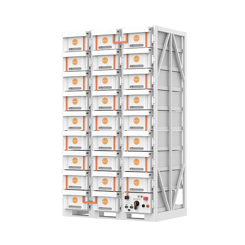
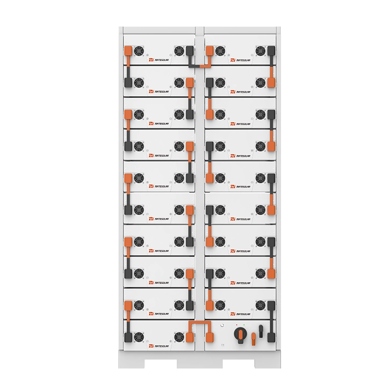
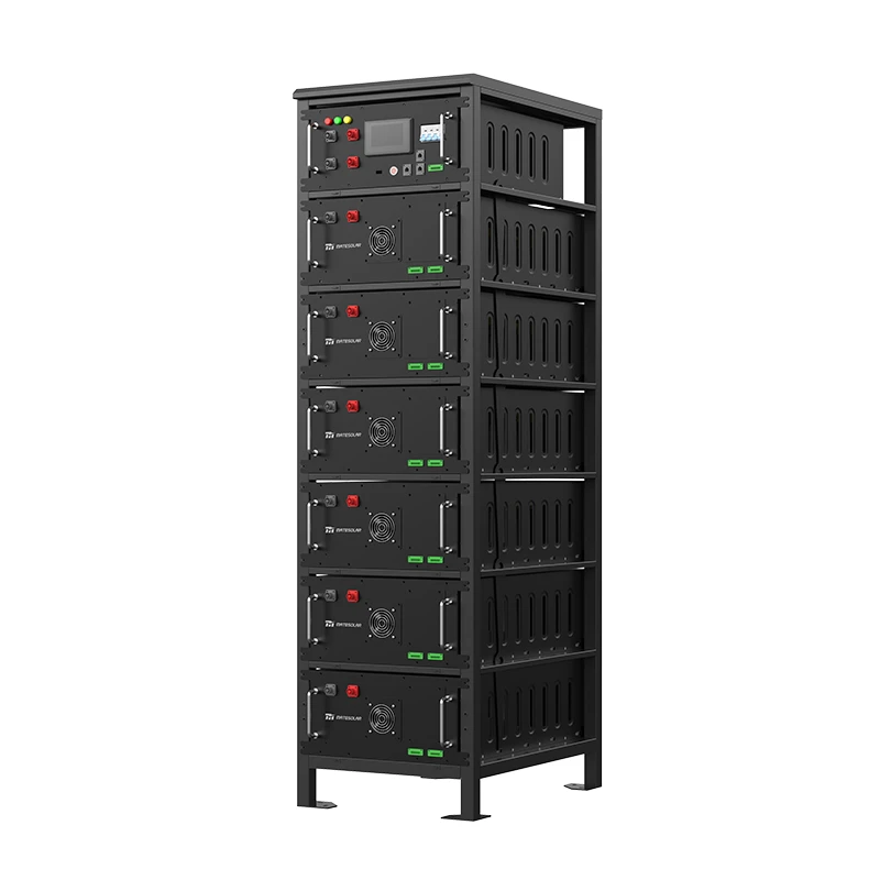
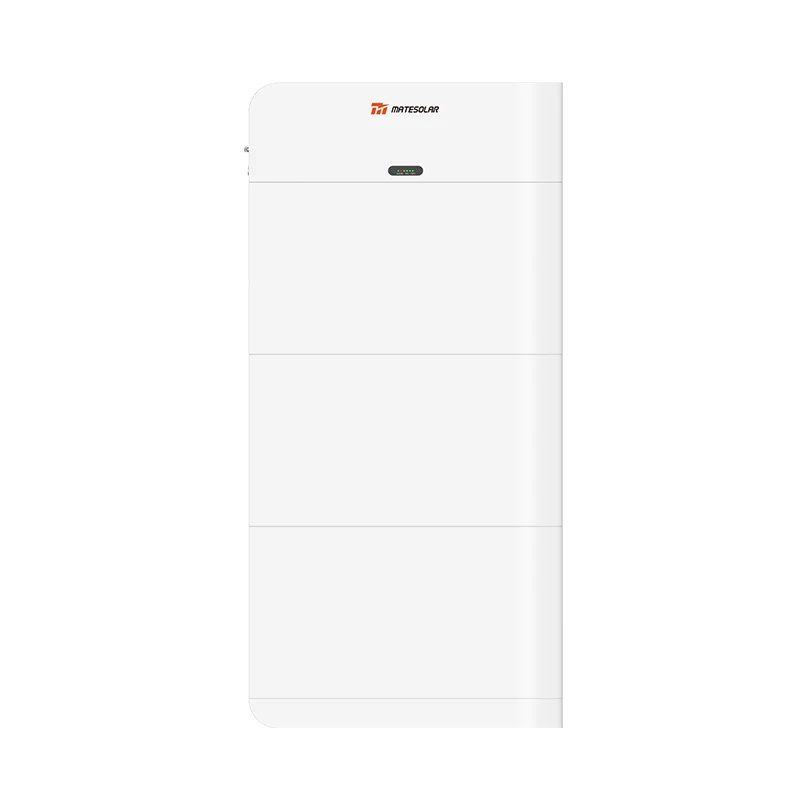
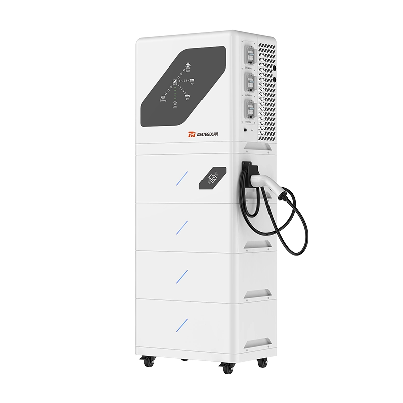
C&I storage in Ukraine is scaling. A 100 kW / 232 kWh or 125 kW / 261 kWh liquid-cooled cabinet is the right architecture for a clinic, a commercial building, or a small industrial load. A 500 kW hybrid solar system, or a 1–2 MWh air-cooled container, or a 3–5 MWh liquid-cooled container, is the architecture for a manufacturing site or a district-level critical facility. As project size grows, the number of parallel converter units grows with it.
Parallel grid-forming operation introduces a failure mode that does not exist in single-unit testing. When multiple voltage-source converters share an islanded load, differences in impedance, control parameters, and load distribution can produce circulating currents, unequal loading, and low-frequency oscillations. The wrong virtual impedance setting can reduce stability margin at low SCR. The loss of one unit in a parallel set—for maintenance, or because of a fault—can cascade if the remaining units are not coordinated to absorb the load step.
So the due-diligence questions become architectural:
Does the grid-forming claim cover N ≥ 2 units in parallel in islanded mode, with a documented load-sharing strategy? Has parallel stability been tested at the lowest credible SCR, not the nominal one? What happens when one unit trips—does the system hold, or does the bus collapse?
A system that passes L2 but fails L3 is not a resilience asset at project scale. It is a collection of individually capable units that cannot be operated together under the conditions that matter.
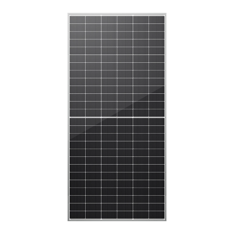
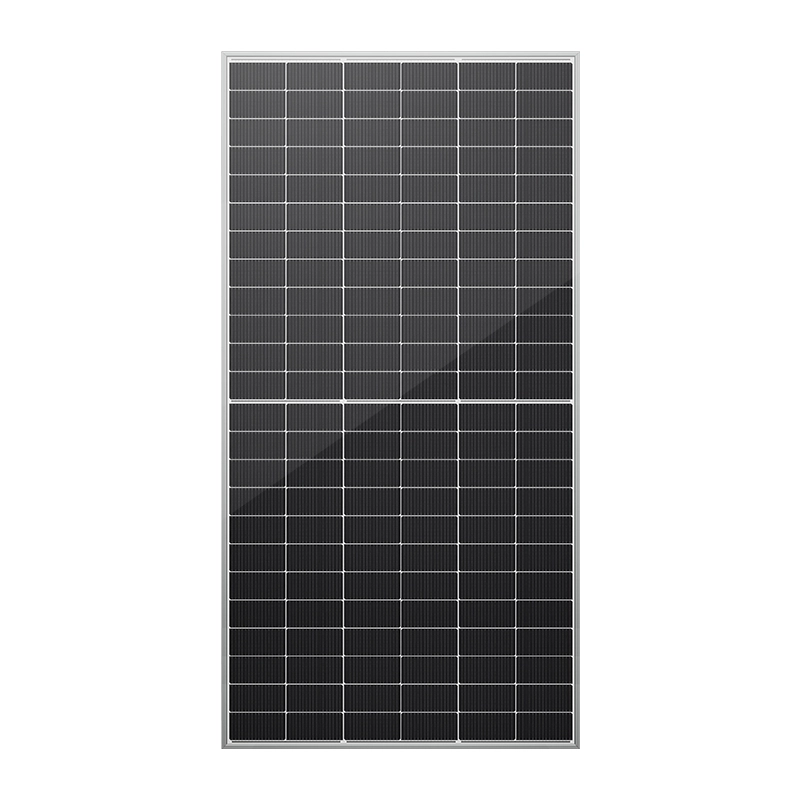
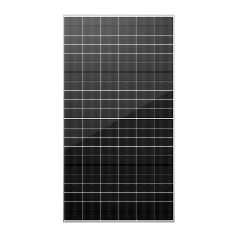
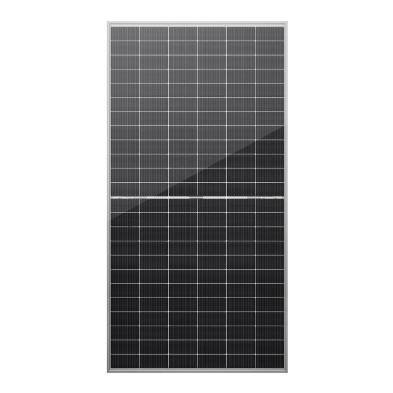
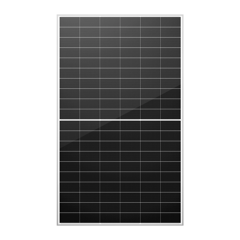
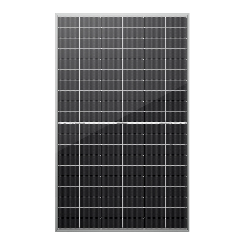
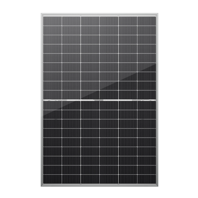
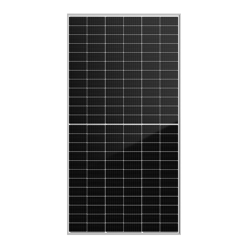
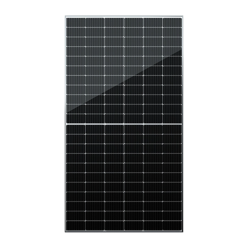
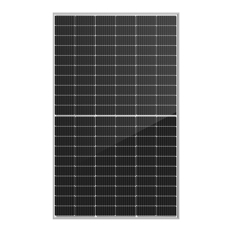
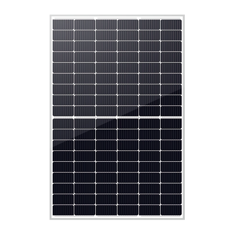
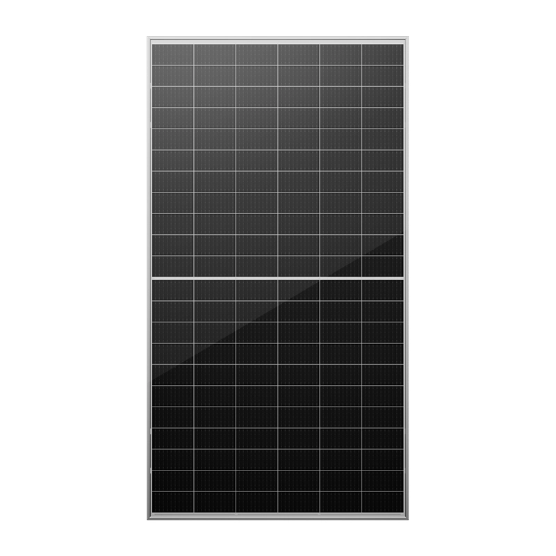
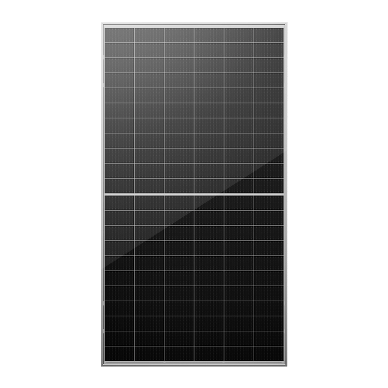
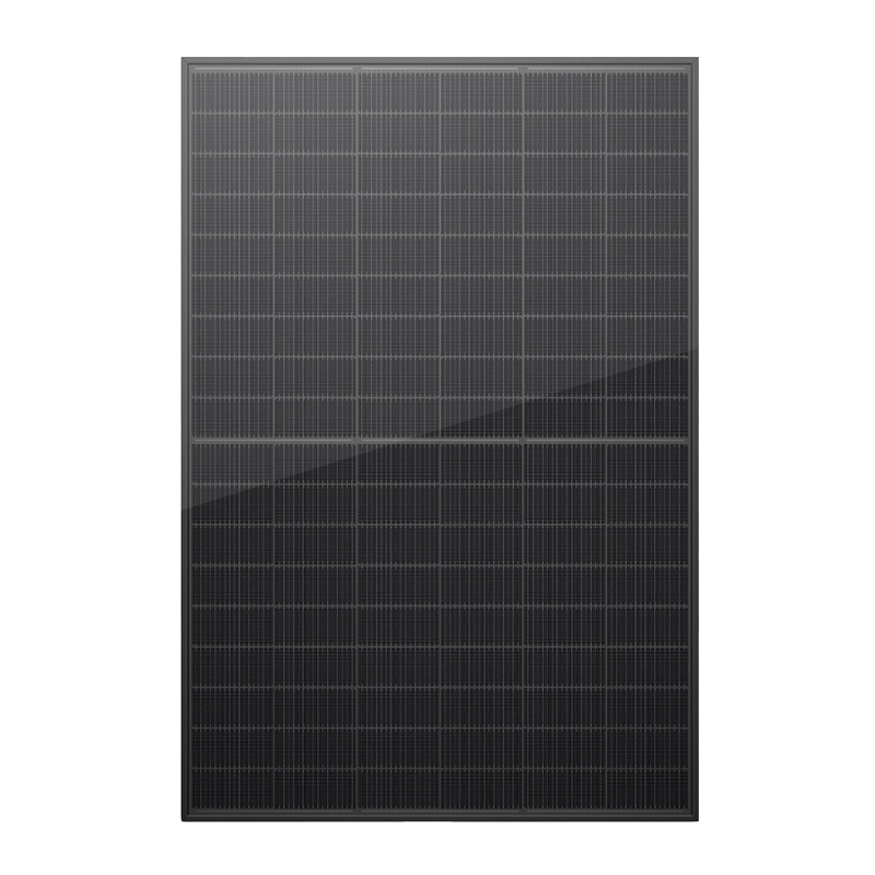
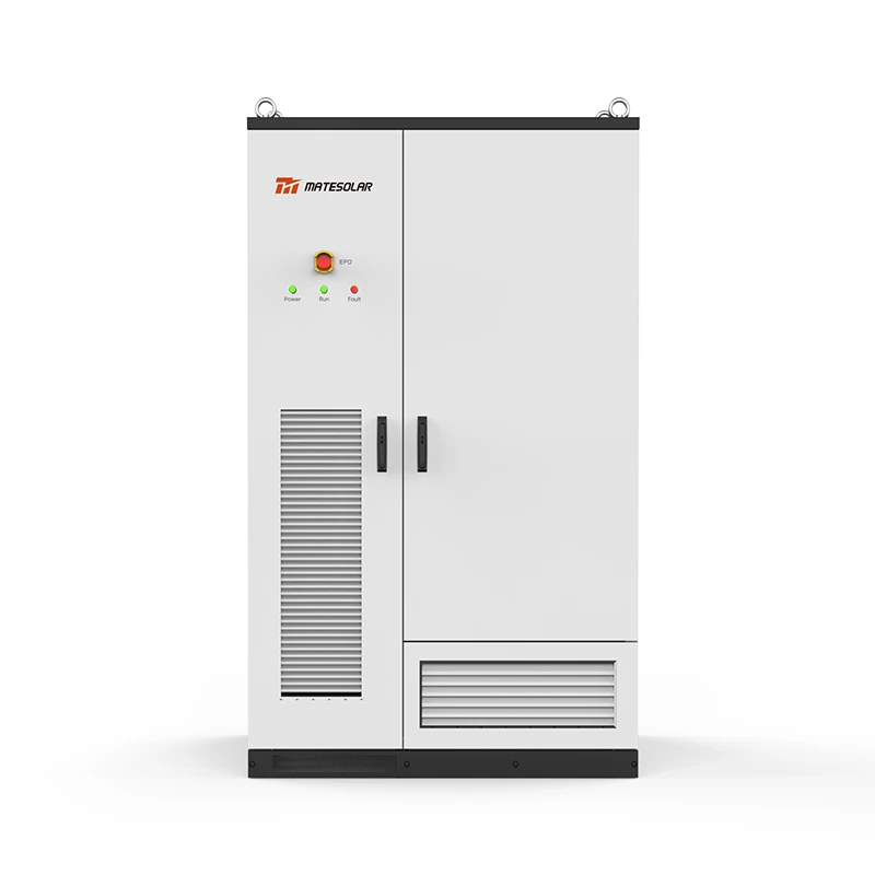
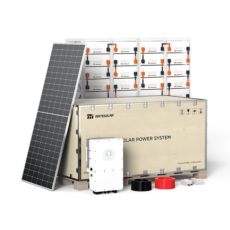
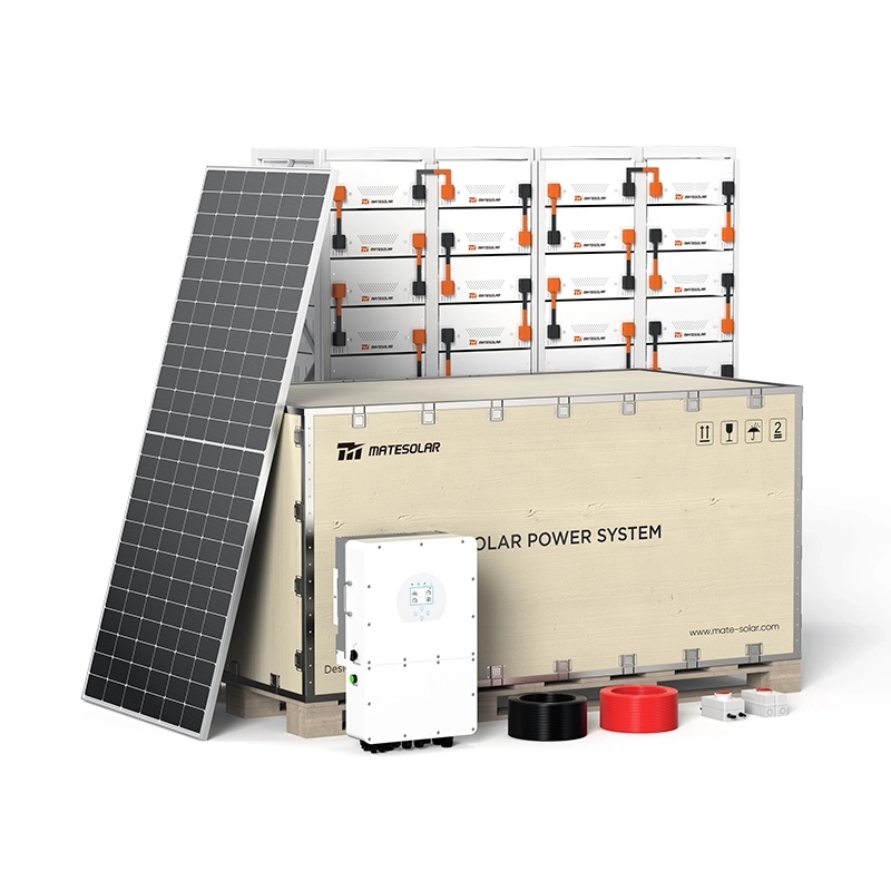
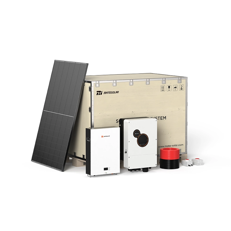
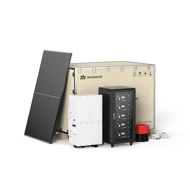
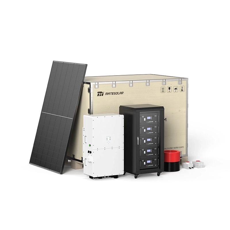
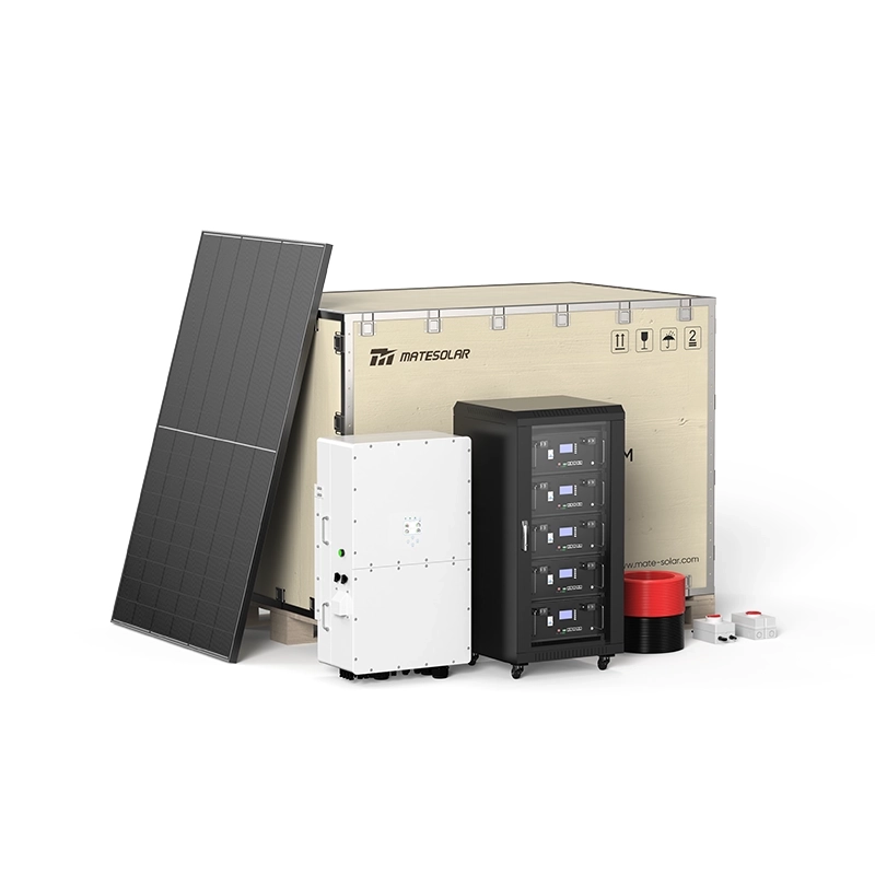
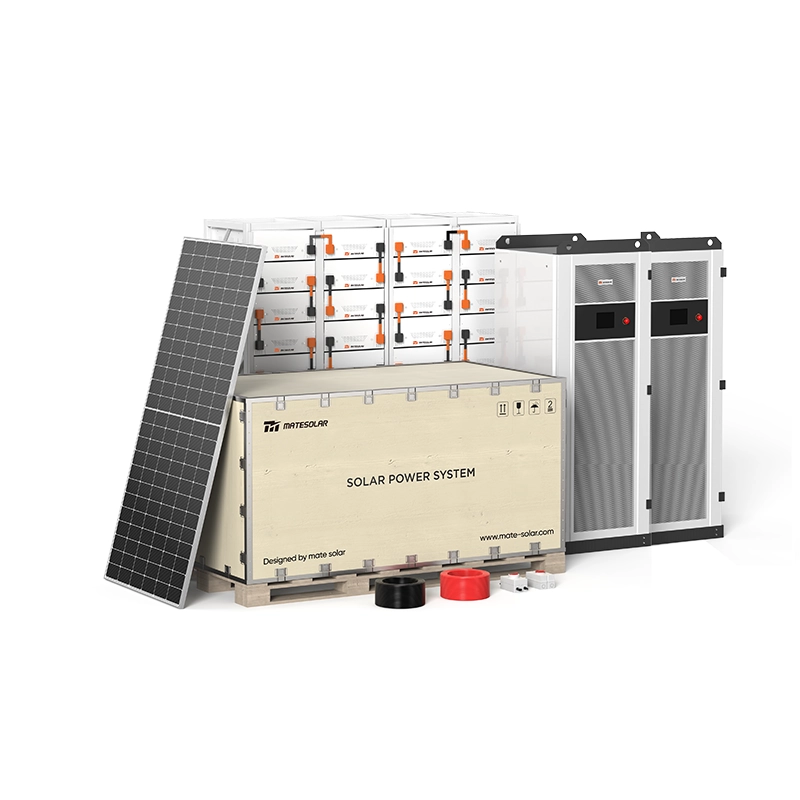
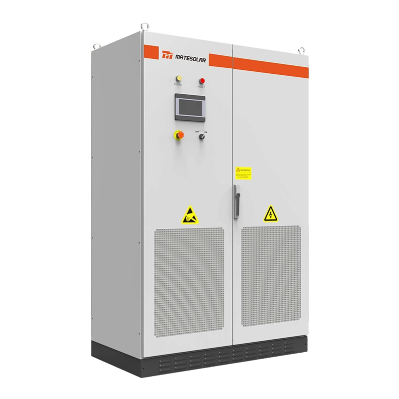
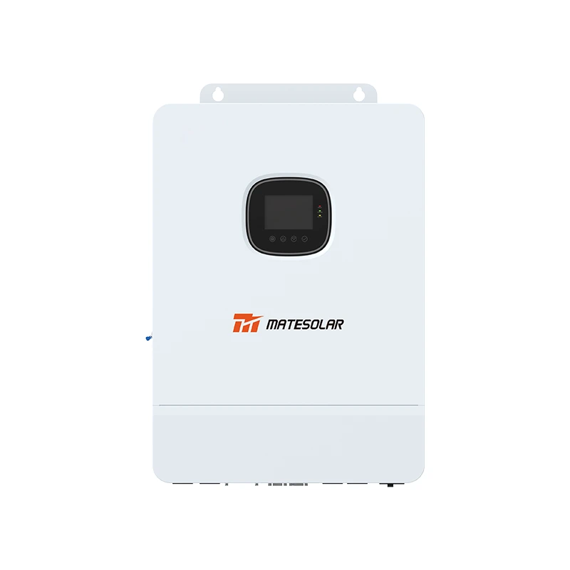
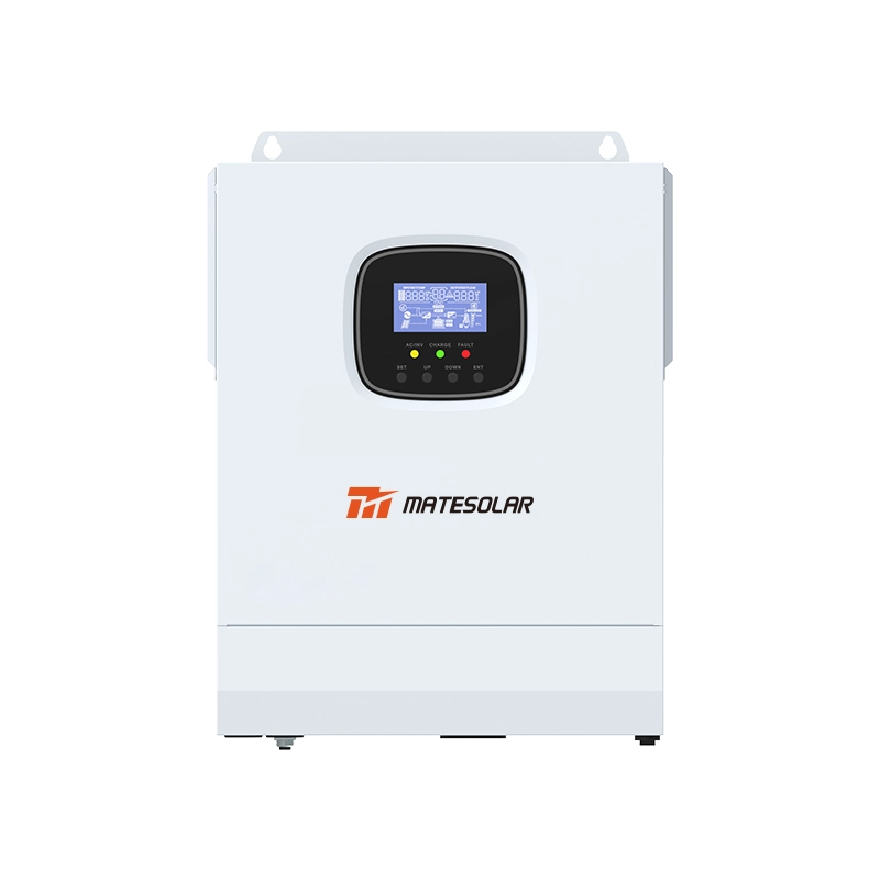
This is where the hybrid architecture question becomes inseparable from the validation question. A Commercial 500 kW Hybrid Solar System integrating PV input, battery storage, and grid-forming output must be evaluated on whether the hybrid controller preserves voltage-source behaviour when the PV input fluctuates and the battery assumes the slack—not just on PV conversion efficiency. If the PV inverter’s grid-following dynamics dilute the storage system’s grid-forming capability at the moment the grid is weakest, the architecture has a validation gap that the converter datasheet will never reveal. The deployment reference for that architecture is available at the Commercial 500 kW Hybrid Solar System product page.
Black start: the line between a backup battery and a grid reconstruction asset
Black start is the most demanding grid-forming function, and it is the one most often confused with “islanded operation.” They are not the same thing. Islanded operation assumes a live reference somewhere. Black start assumes nothing—zero voltage, zero frequency, no external source to synchronize to. The storage system must energize the bus, establish a reference, and then accept load in a controlled sequence.
A grid-following converter cannot do this by definition. A grid-forming converter with a black-start function can—but only if the auxiliary power architecture allows the converter to start when the grid is absent. A container that can black-start a bus but cannot sustain its own auxiliaries during the startup sequence is an L3 system masquerading as L4.
The field evidence from comparable deployments shows what a real L4 record looks like. A 2.5 MW / 10 MWh grid-forming system in Coqên County, Tibet, underwent a black-start field test that validated “the full sequence of independent voltage-frequency reconstruction and load restoration without external grid support.” That is not a simulation. It is a sequence record.
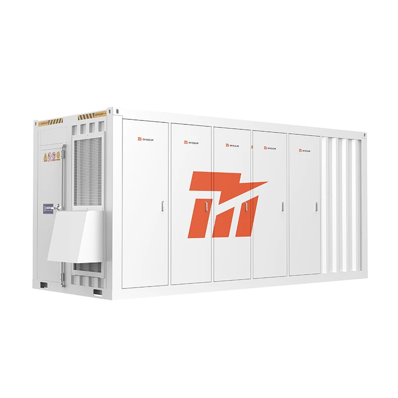
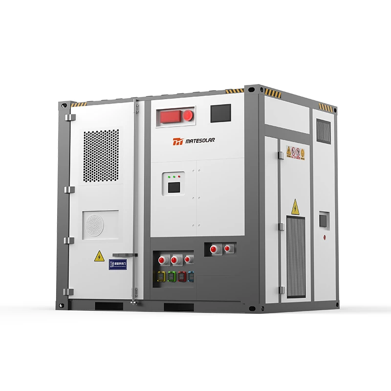
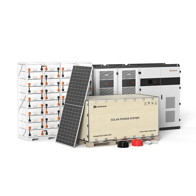
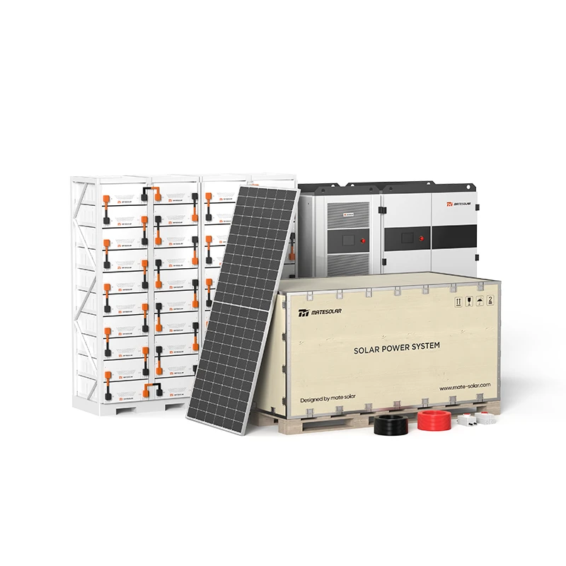
For a Ukrainian hospital, a water utility, or a continuous-process industrial site, the question is the same: has the black-start sequence been performed as a field test, and what was the load restoration profile? At container scale—a 40ft 1MWh / 2MWh Air-Cooled Container ESS or a 20ft 3MWh / 5MWh Liquid Cooling Container ESS—black start is a system-architecture property, not a converter property. The container must establish auxiliary power, energize the internal bus, and coordinate multiple parallel converters before the output breaker closes. The validation evidence to request is a field or witnessed sequence record, not a datasheet statement. Deployment references for these platforms are available at the 40Ft 1MWh 2MWh Air-Cooled Container ESS product page and the 20ft 3MWh 5MWh Liquid Cooling Container ESS product page.
The 20 ms question, and the loads it has to survive
A stated transfer time of 20 ms is a useful benchmark. It is specific enough to be tested, which already puts it ahead of a vague “seamless transfer” claim. But it is not a validation conclusion.
The first follow-up is: 20 ms at what load condition? A transfer time measured at no load or resistive load is not equivalent to a transfer time measured with a motor step, where inrush current and electromagnetic transients interact with the grid-forming control loop. The second is: at what upstream SCR? A transfer that is clean at SCR = 3 may exhibit a frequency undershoot or a transient overcurrent at SCR = 1.5.
The relevant evidence is not a single figure. It is a family of records across load types (resistive, motor, rectifier), load steps (0–50%, 50–100%), and grid conditions. A single 20 ms number is the start of due diligence, not the end.
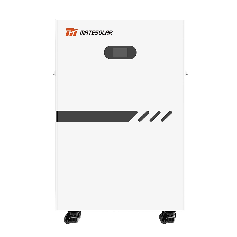
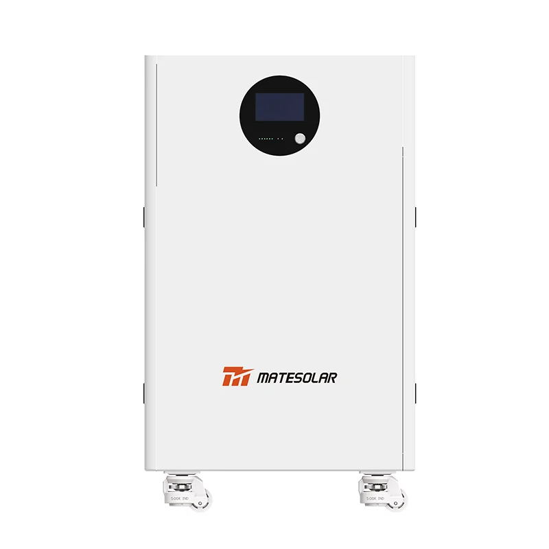
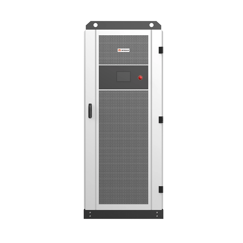
This matters most at the distribution edge, which is exactly where the 100 kW / 232 kWh and 125 kW / 261 kWh liquid-cooled cabinet class is deployed—and exactly where the SCR is lowest and the critical load is most sensitive to a transfer gap. A cabinet rated for 125 kW whose transfer strategy assumes a moderately strong grid is a cabinet whose resilience value is conditional. The validation question is whether the cabinet’s grid-forming control and transfer sequence have been tested at the SCR conditions the site will actually present. Product references for this class are available at the 100kW 232kWh/ 125kW 261kWh Liquid-Cooled Outdoor Cabinet product page.
Winter makes validation a moving target
The Ukrainian grid does not present a constant SCR. Winter adds a second-order fragility that a summer commissioning test cannot capture. Ice loading, conductor galloping, and substation damage can remove parallel paths and change effective grid impedance at a downstream connection point within hours.
A grid-forming system validated only at a fixed SCR is therefore only partially validated for Ukraine. The L5 question is whether the control strategy can adapt as the grid weakens: whether virtual impedance, droop coefficients, or inner-loop bandwidth can be adjusted—automatically or through commissioning parameters—to maintain stability as the SCR falls from 2.5 to 1.5 to 1.
The research on adaptive smooth switching for multi-machine parallel virtual synchronous generator systems confirms that grid-strength variation is a first-order design problem, not a tuning afterthought. The buyer’s question is direct: does the supplier offer a documented control-adaptation strategy for SCR variation, and is it evidenced by field data across seasons or grid conditions?
A procurement checklist that asks for evidence, not adjectives
The framework above translates into ten items a Ukrainian C&I buyer can put in front of a supplier.
Table 3: Grid-forming validation checklist for Ukrainian C&I storage procurement, November 2026
| # | Item | Minimum acceptable evidence | Red flag |
| 1 | SCR envelope | Documented minimum SCR with test or field data | “Grid-forming capable” with no SCR figure |
| 2 | Low-SCR unit test | Factory or field test at SCR ≤ 1.5, with voltage and frequency waveforms | Test only at SCR ≥ 3 |
| 3 | Multi-unit parallel stability | PHIL or field data for N ≥ 2 in islanded mode, including load-sharing and circulating-current data | Parallel capability asserted without stability data |
| 4 | Black-start sequence | Field record of voltage/frequency reconstruction and load restoration from a dead bus | “Black-start ready” without a sequence record |
| 5 | Transfer time under load | Transfer measured with motor or step load, at the site’s credible SCR | No-load or resistive-load-only transfer time |
| 6 | Adaptive control | Documented strategy for SCR variation; field data across grid conditions | Fixed-parameter control presented as sufficient |
| 7 | Auxiliary power resilience | Evidence that auxiliaries remain powered during black start and islanded operation | Auxiliary supply dependent on the grid |
| 8 | Protection coordination | Grid-forming fault-current contribution characterized and coordinated with upstream protection | No fault-current data for grid-forming mode |
| 9 | Import conformity | CE marking; UN38.3 and MSDS; confirmed HS-code classification for the tax exemption | Assumption that all storage-related equipment is automatically exempt |
| 10 | Support pathway | Documented remote diagnostics, spare-parts logistics, and on-site commissioning availability for large projects | No defined model for software or hardware remediation |
The checklist is deliberately weighted toward items 3, 4, and 5—the L3–L5 evidence. A supplier that can satisfy 1, 2, and 9 but not 3, 4, and 5 is offering a grid-forming product, not a validated resilience system.
On item 9, a note of caution. The customs and VAT exemption for energy equipment is confirmed through the end of 2028, but its applicability depends on HS-code classification and technical characteristics, not on a product’s marketing category. Lithium-ion batteries under HS code 8507 60 00 00 with a capacity of at least 100 Ah fall within the preferential list, but the benefit’s application depends on the legally established characteristics of the specific goods. CE marking, UN38.3, and MSDS are baseline documentation requirements independent of the tax question. A procurement that assumes blanket exemption without confirming classification is a procurement that may discover a cost surprise after the technical decision is already made.
Item 10 reflects a practical reality that is often left out of technical guides. Ukraine is a market where many C&I buyers do not have a local installation or repair team, and where the supplier may not either. That does not change the validation standard; it changes the support model that has to sit alongside it. For hardware quality issues, the workable pathway is parts shipment with remote-guided replacement, or product replacement for severe failures. For software issues, remote technical diagnosis is the first line. For large C&I projects, on-site commissioning support can be arranged when the scale and technical complexity justify it. A validated system without a defined support pathway is a resilience asset with an unresolved operational dependency.
The 2027 question is narrower than it looks
The system procured in the current window will be commissioned in late 2026 or early 2027 and will operate through at least the 2027/28 winter. The validation question is therefore forward-looking: will the evidence that supports the procurement decision still describe the system’s operating envelope after a winter of grid degradation?
Three things make the window tighter than a normal procurement cycle would suggest.
The regulatory unblocking is front-loaded. Flexible connection, shared connection, and the land/zoning deregulation are designed to accelerate commissioning now. The administrative pathway is open, but the technical evidence required to use it lawfully is the binding constraint. A project that obtains a flexible connection without a system that can operate under the flexible-connection technical conditions has cleared the wrong hurdle.
The grid’s physical trajectory is not improving at the same rate as the administrative pathway. The capacity deficit persists, and transmission-node vulnerability persists. A system validated against a 2026 grid condition may face a weaker grid in 2027. The adaptive-control layer is the only layer that explicitly addresses that trajectory.
And the import regime is stable but not uniform. The exemption runs through 2028, but the HS-code and technical-characteristic conditions mean the documentation work has to happen before the commercial commitment, not after.
FAQ
We’ve been told grid-forming is standard on many commercial systems. Why does validation depth matter if the feature is there?
Because the feature is a firmware attribute, not a system behaviour. A converter can contain a grid-forming algorithm and still fail at SCR = 1.2 when two units are in parallel and a motor steps from 20% to 80%. The relevant question is whether the system—converter, battery, EMS, switching architecture, and parallel coordination—has been tested at the site’s credible SCR with the load profile the site will actually present. Standardized grid-forming testing protocols do not yet exist, so the evidentiary burden sits with the supplier and the buyer’s technical team.
Our site is at SCR ≈ 2.5 today. Do we really need a system validated at SCR = 1?
The SCR at a Ukrainian C&I site is not a fixed parameter. Line damage, substation loss, or the removal of parallel paths can change effective grid strength at a downstream connection point over the asset’s life. A system validated only at SCR = 2.5 has an operating envelope that does not cover the credible range of the site’s future conditions. The procurement standard should be the lowest credible SCR over the resilience horizon, not the measured value on survey day.
What’s the difference between single-unit and multi-unit grid-forming, and why does it matter for a 500 kW project?
A 500 kW project typically uses multiple converter units in parallel. Single-unit validation shows one converter can establish a reference under defined conditions. Multi-unit validation shows the converters can share load, manage circulating currents, and remain stable when the number of units changes—for example, when one trips. The stability boundary for a parallel system is different, because aggregated grid strength changes and inter-unit dynamics introduce new modes. A single-unit validation is not a validation for the parallel architecture the project will operate.
How should we read a “20 ms seamless transfer” claim?
As a starting point. The follow-ups are: 20 ms at what load (resistive, motor, rectifier), at what upstream SCR, and with what load step? A no-load or resistive-load transfer time is not equivalent to a motor-step transfer time. Ask for a family of records across load types and SCR conditions.
Our project is a 1 MWh container. Does black start come automatically with grid-forming converters?
No. Black start is a system-level sequence. The container must establish auxiliary power, energize the internal bus, and accept load in a controlled sequence without an external reference. A container can contain grid-forming converters and still fail to black-start if its auxiliaries depend on the grid. Ask for a field or witnessed sequence record with the load restoration profile.
We don’t have a local installation or repair team. How does that fit with the validation model?
Validation and support are complementary, not interchangeable. A system that passes L3–L5 is more likely to run without intervention, but it still needs a defined pathway for diagnostics, firmware, and hardware remediation. The practical model is parts shipment with remote-guided replacement for hardware, product replacement for severe failures, and remote technical guidance for software. Large C&I projects can justify on-site commissioning support when the scale and complexity require it. The checklist includes the support pathway as a separate item for exactly this reason.
Can we assume our storage equipment is exempt from import duty and VAT?
The exemption is real through 2028, but applicability depends on HS-code classification and technical characteristics, not the product’s marketing description. Confirm the HS code and technical classification for each major component before the commercial commitment. CE marking, UN38.3, and MSDS are baseline requirements independent of the tax question.
The resilience asset is the validated system, not the cabinet
Ukraine’s C&I storage market in November 2026 sits inside a paradox. The administrative barriers to installing storage have never been lower. The physical and evidentiary barriers to operating storage as a resilience asset have never been higher.
The first principle remains what SolarPower Europe and SEAU said it was: energy security first, economics second. But that principle only becomes operational when the system can show—at the validation depth the grid actually requires—that it will start when the grid is absent, hold voltage and frequency at the site’s credible SCR, coordinate multiple units in parallel, transfer load without a gap that critical equipment cannot tolerate, and adapt as the grid weakens over the asset’s operating life.
A battery cabinet with a grid-forming label is not yet a resilience asset. A validated system is.
MateSolar is a one-stop solar and storage solutions provider serving C&I customers in high-fragility grid environments. The validation-depth framework in this guide reflects the technical due-diligence standard MateSolar applies across its grid-forming cabinet, container, and hybrid system platforms—from the 100 kW / 232 kWh and 125 kW / 261 kWh distributed-edge cabinets to the 1 MWh / 2 MWh air-cooled and 3 MWh / 5 MWh liquid-cooled container systems and the 500 kW hybrid solar architecture. For Ukrainian C&I buyers, the question is not whether storage will be part of the resilience plan. The question is whether the system chosen can prove it will operate when the plan is tested.