










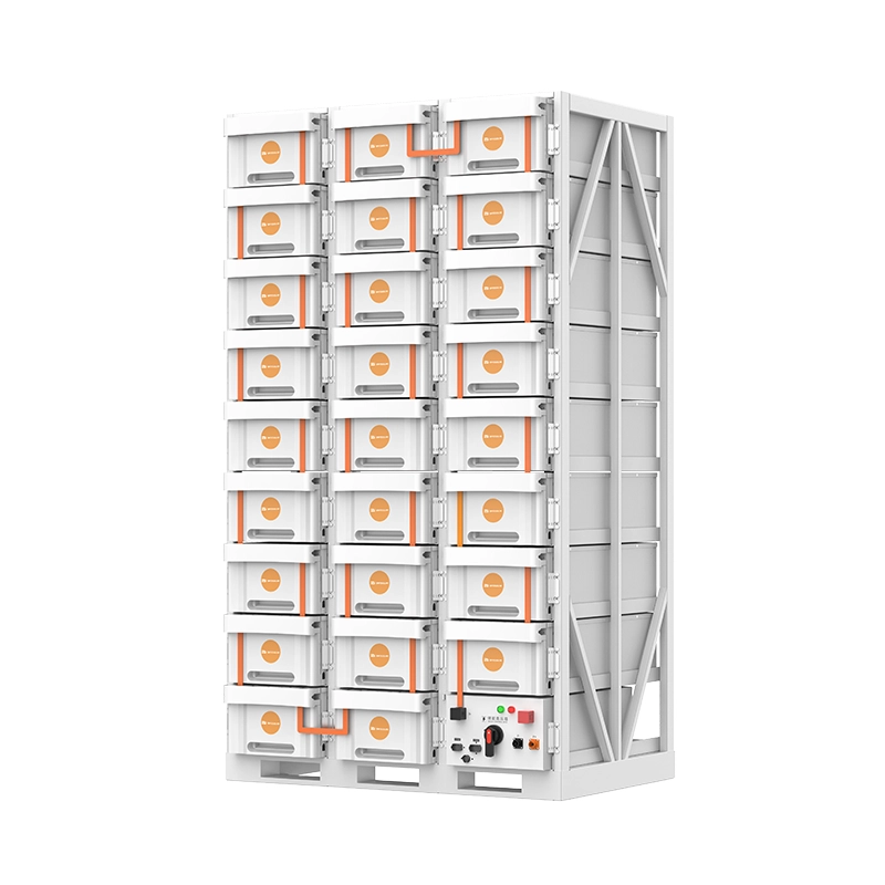
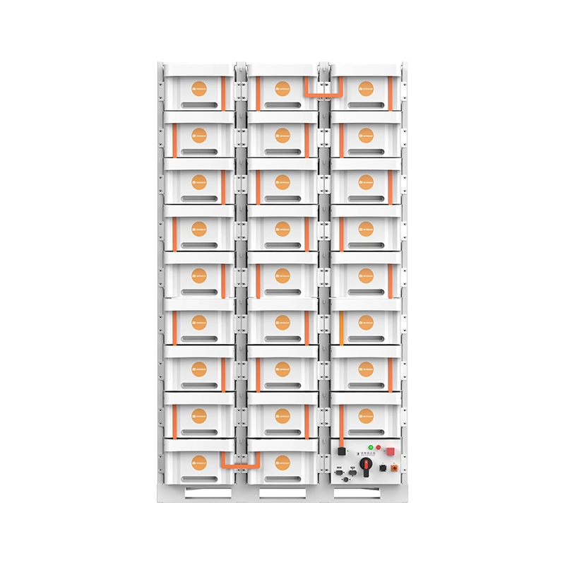
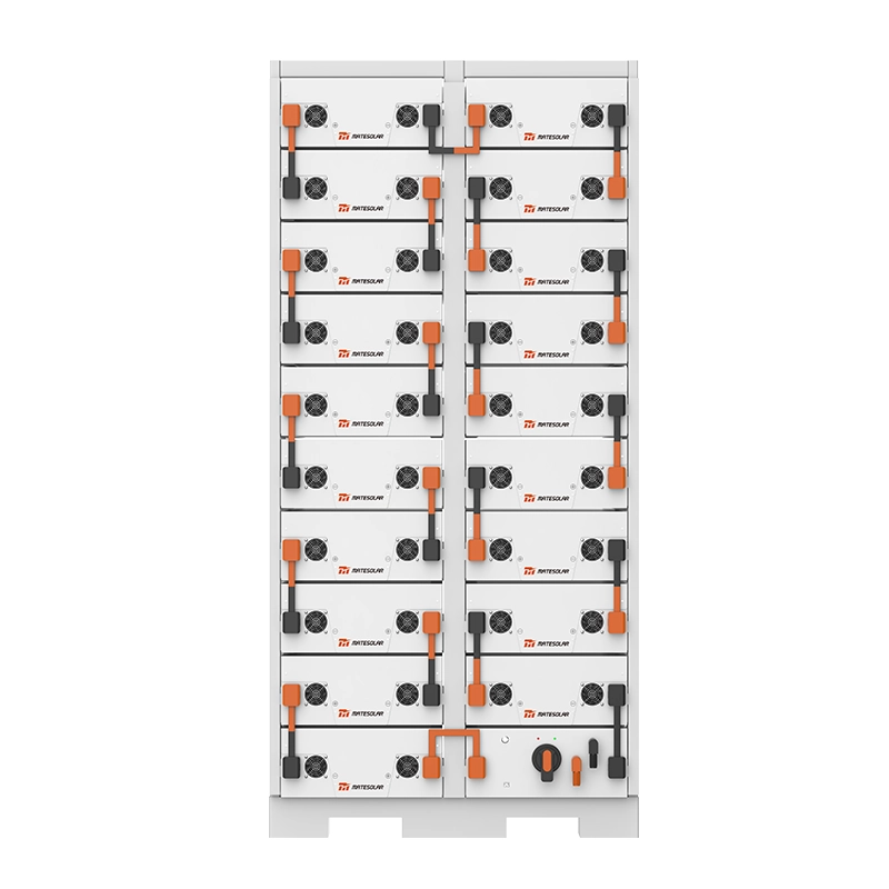
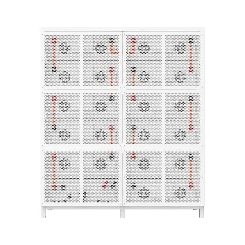






Усередині стандартної конфігурації, що визначає комерційні та промислові накопичувачі енергії у 2026 році: архітектура, інженерне обґрунтування, розбір компонентів та конкурентний аналіз
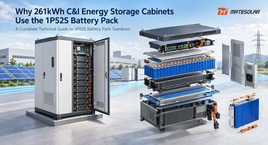
У 2026 році рідинноохолоджувана шафа накопичення енергії місткістю 261 кВт·год стала фактичним стандартом для комерційних і промислових систем зберігання енергії на акумуляторах (BESS). Незалежно від того, чи розглядаєте ви продукцію китайських виробників першого рівня, європейських інтеграторів чи північноамериканських постачальників, показник місткості 261 кВт·год і конфігурація акумуляторної батареї 1P52S з'являються з вражаючою послідовністю. Ця конвергенція не є випадковою. Вона є результатом вирішення численних інженерних обмежень — вікон напруги постійного струму PCS, стандартизації форм-факторів елементів, вимог до терморегуляції та оптимізації логістики — в єдину конфігурацію, яка забезпечує найкращий баланс продуктивності, безпеки та вартості для комерційного та промислового сегментів.
Цей посібник містить повний технічний аналіз акумуляторної батареї 1P52S: її архітектуру, інженерне обґрунтування вибору, детальний розбір на рівні компонентів, порівняння з альтернативними конфігураціями, міркування щодо управління тепловим режимом, проєктування безпеки та економічні фактори, які роблять її галузевим стандартом. Незалежно від того, чи є ви розробником проєктів, підрядником за договором EPC, менеджером із технічних закупівель чи оператором промислового об'єкта, який оцінює варіанти систем накопичення енергії (BESS), цей документ є вичерпним довідником для розуміння того, чому 261 кВт·год і 1P52S є нероздільними на сучасному ринку комерційних і промислових систем зберігання енергії.
Частина 1: Що таке 1P52S? Пояснення базової архітектури
1.1 Визначення та номенклатура
Позначення "1P52S" описує електричну топологію акумуляторної батареї. "P" означає паралельне з'єднання, а "S" — послідовне. У конфігурації 1P52S 52 окремі акумуляторні елементи з'єднані послідовно, без жодних паралельних з'єднань усередині батареї. Це означає, що батарея має єдиний послідовний ланцюжок із 52 елементів.
Кожна комірка в збірці 1P52S є літій-залізо-фосфатною (LFP) призматичною коміркою з номінальною напругою 3,2 В і ємністю 314 А·год. Ці комірки на 314 А·год стали домінуючим вибором для комерційних, промислових та комунальних стаціонарних систем зберігання енергії завдяки оптимальному балансу густини енергії, ресурсу циклів, безпеки та вартості.
1.2 Розрахунки напруги та ємності
Електричні параметри збірки 1П52С безпосередньо випливають із її послідовного з'єднання:
Номінальна напруга батареї:
3.2В (номінальна напруга елемента) × 52 (елементи послідовно) = 166.4В постійного струму
Номінальна ємність батареї:
314Агод (ємність комірки, оскільки є лише одна паралельна гілка)
Номінальна енергія батареї:
166,4 В пост. струму × 314 А·год = 52,25 кВт·год
Діапазон робочої напруги:
При типовому діапазоні робочої напруги комірки LFP від 2,5 В до 3,65 В діапазон напруги батареї становить:
- Мінімум: 2,5В × 52 = 130В постійного струму
- Максимум: 3.65В × 52 = 189.8В пост. струму
Системна конфігурація для 261 кВт·год:
П'ять збірок 1P52S, з'єднаних послідовно:
- Номінальна напруга системи: 166.4В × 5 = 832В постійного струму
- Енергія системи: 52,25 кВт·год × 5 = 261,25 кВт·год
- Позначення системи: 1P260S (5 упаковок по 52 елементи)
1.3 Чому саме точка ємності 261 кВт·год?
Точка ємності 261 кВт·год природним чином випливає з конфігурації 1P52S. Кожен блок забезпечує приблизно 52,25 кВт·год. П'ять блоків послідовно дають 261,25 кВт·год. Ця конфігурація точно відповідає вимогам до напруги постійного струму струнових перетворювачів PCS, які зазвичай використовуються в комерційних та промислових застосуваннях.
Взаємозв'язок між конфігурацією акумуляторної батареї, напругою системи та сумісністю з PCS узагальнено в наступній таблиці:
| Параметр | Одинарна упаковка | Система з 5 блоків (261 кВт-год) | Примітки |
| Конфігурація | 1P52S | 1P260S (5×1P52S) | П'ять пачок поспіль |
| Номінальна напруга | 166,4 В постійного струму | 832 В пост. струму | Помножене на 5 |
| Діапазон напруги | 130–189.8 В постійного струму | 650–949 В постійного струму | Поєднується з вікном PCS DC |
| Номінальна енергія | 52,25 кВт·год | 261,25 кВт·год | Промисловий стандарт місткості |
| Кількість клітин | 52 | 260 | Акумуляторні елементи LFP ємністю 314 А·год |
Промислові стандартні специфікації для рідинноохолоджуваних промислово-комерційних шаф ємністю 261 кВт·год
Частина 2: Інженерне обґрунтування — Чому 1P52S?
Обмеження вікна напруги постійного струму PCS
Найважливішим інженерним чинником, що зумовлює конфігурацію 1P52S, є діапазон напруги постійного струму перетворювачів електроенергії (PCS) стрінгового типу, які використовуються в комерційних і промислових (C&I) застосуваннях.
Для струнного PCS із виходом змінного струму 400 В діапазон напруги з боку постійного струму зазвичай становить від 600 В до 1000 В постійного струму. BESS має працювати виключно в межах цього діапазону, щоб забезпечити повну потужність заряджання та розряджання без обмеження потужності (кліпінгу) або вимикання PCS.
Конфігурація 1P52S із п'ятьма блоками послідовно забезпечує діапазон напруги від 650 В постійного струму до 949 В постійного струму (на основі діапазону напруги елемента від 2,5 В до 3,65 В). Цей діапазон зручно вписується у вікно PCS 600–1000 В постійного струму, що забезпечує повну глибину розряду та повний стан заряду без експлуатаційних обмежень PCS.
Розгляньте альтернативи:
- Конфігурація серії з 4 модулів (1P208S) створюватиме діапазон напруги приблизно 520–759 В постійного струму, що є нижчим за мінімальне значення PCS у 600 В постійного струму на нижній межі, що унеможливлює повне розряджання.
- Конфігурація серії з 6 модулів (1P312S) створюватиме діапазон напруги приблизно 780–1000 В постійного струму, що перевищує максимум PCS у 1000 В постійного струму на верхній межі, перешкоджаючи повному заряду.
Конфігурація з 5 штук — це єдиний варіант кількості модулів, який повністю задіює діапазон напруги PCS, не перевищуючи жодної з меж.
2.2 Порівняння конфігурацій пакетів
| Конфігурація | Напруга акумуляторної батареї | Енергія пачки | Клітин в упаковці | Комплекти послідовних акумуляторів для 261 кВт·год | Діапазон напруги системи | Сумісність із ПК |
| 1P48S | 153,6 В | 48,23 кВт·год | 48 | 5,4 (не ціле) | / | Нестандартний |
| 1P52S | 166,4 В | 52,25 кВт·год | 52 | 5 | 650–949 В постійного струму | Оптимальний |
| 1P104S | 332,8 В | 104,5 кВт·год | 104 | 2,5 (не ціле) | / | Тільки промисловий масштаб |
Технічні характеристики рідинноохолоджуваного акумуляторного блоку Eneroc; стандартні конфігурації галузі
Таблиця показує, чому 1P52S є єдиною конфігурацією, яка дає цілу кількість акумуляторних блоків для цільового показника 261 кВт·год із збереженням сумісності з PCS. Конфігурація 1P48S вимагала б 5,4 блока, що не є дійсним цілочисельним значенням кількості послідовних з'єднань. Конфігурація 1P104S, хоч і пропонує вищу густину енергії на блок, вимагає лише 2,5 блока для 261 кВт·год — що знову ж таки не є цілим числом.
2.3 Стандартний режим заряджання/розряджання 0,5P
Системи накопичення енергії для комерційного та промислового сектору (C&I BESS) майже завжди проектуються з коефіцієнтом заряду/розряду 0,5P. Для системи ємністю 261 кВт·год це відповідає номінальній потужності приблизно 130 кВт. Система перетворення енергії (PCS) потужністю 125 кВт, яка зазвичай використовується в парі з шафами на 261 кВт·год, працює на трохи нижчій за 0,5P потужності, забезпечуючи консервативний запас працездатності.
Швидкість 0.5P відповідає можливостям елементів LFP ємністю 314 А·год, які оптимізовані для енергетичних застосувань, а не для високої потужності. При 0.5P елемент на 314 А·год забезпечує струм заряду або розряду 157 А, що цілком в межах безпечного діапазону його експлуатації.
Стандартизація формату клітинок
Призматичний літій-залізо-фосфатний акумулятор (LFP) ємністю 314 А·год досяг загальногалузевої стандартизації за розмірами, робочими характеристиками та виробничими процесами. Ця стандартизація є результатом багаторічної еволюції акумуляторів ємністю 280 А·год, які домінували на ринку впродовж 2023–2024 років.
Акумулятор ємністю 314 А·год забезпечує приблизно на 12% більшу ємність, ніж акумулятор на 280 А·год у тому ж фізичному форматі, що дає змогу підвищити щільність енергії без зміни розмірів батареї чи виробничого обладнання. Така зворотна сумісність стала ключовим чинником швидкого переходу галузі на елементи 314 А·год та конфігурацію 1P52S.
Частина 3: Розбір акумуляторного блоку 1P52S — Покомпонентний аналіз
3.1 Огляд архітектури пакета
Акумуляторний блок 1P52S складається з двох модулів 1P26S, з'єднаних послідовно. Кожен модуль містить 26 елементів, з'єднаних послідовно. Така модульна конструкція спрощує виробництво, тестування та обслуговування.
Основними компонентами комплексу 1П52С є:
| Компонент | Функція | Типовий матеріал / Технологія |
| Клітини | Накопичення енергії | LFP призматичний, 3.2В, 314Агод |
| CCS | Підключення до стільникової мережі та прийом сигналу | Інтегрований FPC/FFC |
| БМУ | Моніторинг та балансування комірок | Друкована плата з мікроконтролером |
| Пластина рідинного охолодження | Теплове управління | Алюмінієвий сплав, змійовиковий канал |
| МСД | Ручне відключення живлення | Корпус із запобіжником та додатковими контактами |
| Pack enclosure | Structural and environmental protection | Aluminum alloy, IP67 |
| Thermal interface material | Heat transfer between cells and cooling plate | Gap filler, thermally conductive adhesive |
| Insulation barriers | Electrical isolation | PET film, aramid paper |
| BMS connectors | Signal and power transmission | High-voltage connectors, signal harness |
Source: Industry teardown analysis; manufacturer technical documentation
3.2 The CCS (Cell Connection System)
The CCS (Cell Connection System) serves two critical functions: it connects the cells electrically and it acquires cell voltage signals for the BMS.
In modern 1P52S packs, the CCS is typically implemented using FPC (Flexible Printed Circuit) technology or a combination of FPC and FFC (Flexible Flat Cable). The FPC replaces traditional wire harnesses and busbars with a single integrated component that provides:
- Voltage sensing: Each cell's voltage is routed to the BMU through the FPC
- Temperature sensing: NTC thermistors are integrated into the FPC at strategic locations
- Structural integration: The FPC provides some mechanical support for the cell interconnections
The FPC approach reduces assembly complexity, improves reliability by eliminating wire connections, and enables automated manufacturing.
3.3 The BMU (Battery Management Unit)
The BMU is the brain of the battery pack. It receives signals from the CCS, processes them into digital data, and communicates with the higher-level BMS.
Key BMU functions include:
- Cell voltage monitoring: All 52 cell voltages are measured and reported
- Temperature monitoring: NTC sensors provide pack temperature data
- Passive balancing: The BMU can discharge individual cells through bleed resistors to equalize state of charge across the pack
- Fault detection: Overvoltage, undervoltage, overcurrent, and overtemperature conditions are detected and reported
- Communication: The BMU communicates with the system BMS via CAN or RS485
The passive balancing capability is particularly important for the 1P52S configuration. Because all 52 cells are in series, any imbalance between cells directly reduces the usable capacity of the pack. The "wooden barrel effect" — where the weakest cell determines the pack's capacity — must be actively managed through balancing.
3.4 The Liquid Cooling Plate
The liquid cooling plate is a defining feature of modern 1P52S packs. In liquid-cooled designs, the cooling plate is integrated into the pack's bottom structure, with a serpentine channel through which coolant flows.
The cooling plate maintains cell temperature uniformity within ±3°C across the pack. This temperature consistency is critical for several reasons:
- Цикл життя: LFP cells degrade faster at elevated temperatures. Maintaining uniform temperature avoids localized hot spots that accelerate aging.
- Capacity consistency: Temperature gradients across cells cause differential self-discharge rates, leading to imbalance.
- Безпека: Uniform cooling reduces the risk of thermal runaway initiation at hot spots.
The cooling plate is typically constructed from aluminum alloy for its combination of thermal conductivity, weight, and cost. The serpentine channel design maximizes the heat transfer surface area while maintaining acceptable pressure drop for the coolant circulation system.
3.5 The MSD (Manual Service Disconnect)
The MSD (Manual Service Disconnect) is a safety-critical component that is often misunderstood. It is the yellow, square connector with a pull handle located on the front of the pack, typically positioned between the two 1P26S modules.
Primary function: The MSD allows maintenance personnel to manually disconnect the battery pack from the system for safe servicing. When the MSD is removed, the pack voltage is divided: the voltage across the exposed terminals drops from 166.4V to approximately 83.2V (half the pack voltage), significantly reducing the risk of electric shock.
Short-circuit protection: The MSD incorporates a high-breaking-capacity fuse (typically kA-level) that provides millisecond-level protection against short circuits. The fuse rating must be coordinated with the cell's maximum short-circuit current and the main circuit's current-carrying capacity.
Interlock protection: During MSD insertion or removal, the auxiliary contacts open before the main power contacts. This signal is sent to the BMS, which immediately opens the main contactors in the high-voltage box. The main circuit is de-energized before the MSD contacts separate, eliminating arc flash risk.
The MSD's three-in-one design — manual disconnect, short-circuit protection, and interlock — makes it an essential safety component that should never be bypassed or substituted.
3.6 Module-Level Construction
Each 1P52S pack is built from two 1P26S modules. The module is the basic building block, containing 26 cells in series, the CCS for those cells, and a portion of the thermal management system.
The modular approach offers several advantages:
- Manufacturing efficiency: Modules can be assembled and tested independently before pack integration
- Serviceability: A failed module can be replaced without scrapping the entire pack
- Logistics: Modules are more easily transported and handled than complete packs
- Стандартизація: The same module design can be used in packs of different configurations
Part 4: 1P52S vs. Alternative Configurations
4.1 1P52S vs. 1P104S
The 1P104S configuration, which is more common in utility-scale containerized systems, offers higher integration density. A 1P104S pack contains 104 cells in series, producing:
- Nominal voltage: 332.8Vdc
- Nominal energy: 104.5kWh
Advantages of 1P104S:
- Fewer packs per system reduces enclosure and structural costs
- Higher energy density per unit volume
- Simpler system-level wiring
Disadvantages of 1P104S for C&I:
- Larger physical dimensions (1P104S packs are approximately 2× the size of 1P52S packs)
- Higher pack voltage requires more robust insulation and safety measures
- Cannot achieve the 261kWh standard configuration with an integer number of packs
- More difficult to handle and install without specialized equipment
For C&I applications where cabinet dimensions and logistics are constrained, the 1P52S configuration is preferred.
4.2 1P52S vs. 1P48S
The 1P48S configuration (48 cells in series, 153.6V nominal, 48.23kWh) was an earlier industry standard based on 280Ah cells. It has been largely superseded by 1P52S for several reasons:
- Voltage window mismatch: A 5-pack 1P48S system produces a voltage range of 600–876Vdc, which is narrower than the 1P52S 5-pack range and less optimized for the full PCS window
- Non-integer pack count: Achieving 261kWh with 1P48S packs requires 5.4 packs, which is not a valid integer series count
- Legacy technology: The 48-cell configuration was designed around 280Ah cells; the industry has standardized on 314Ah cells and the 52-cell configuration
4.3 Configuration Comparison Table
| Параметр | 1P48S | 1P52S | 1P104S |
| Cells per pack | 48 | 52 | 104 |
| Номінальна напруга | 153,6 В | 166,4 В | 332,8 В |
| Pack energy | 48,23 кВт·год | 52,25 кВт·год | 104,5 кВт·год |
| Packs for 261kWh | 5.4 (invalid) | 5 (valid) | 2.5 (invalid) |
| System voltage range | 600–876Vdc | 650–949 В постійного струму | 650–949 В постійного струму |
| Primary application | Legacy C&I | Standard C&I | Utility container |
| Pack weight | ~310kg | ~335kg | ~665kg |
| Handling requirements | Forklift | Forklift | Crane/telehandler |
Source: Manufacturer specifications; industry standard configurations
Part 5: Thermal Management — The Liquid Cooling Advantage
5.1 Why Liquid Cooling for 1P52S?
The 1P52S configuration, with its relatively large number of cells in close proximity, demands effective thermal management. Air cooling, while simpler and lower cost, cannot maintain the temperature uniformity required for optimal LFP cell performance and longevity in C&I applications.
Liquid cooling offers several decisive advantages:
- Temperature uniformity: Liquid cooling maintains cell-to-cell temperature difference within ±3°C, compared to ±5-8°C for air cooling
- Higher heat transfer coefficient: Liquid coolants have 10-100× higher heat transfer coefficients than air
- Compact form factor: Liquid cooling plates are integrated into the pack structure, saving space compared to air cooling ducts and fans
- Noise reduction: Liquid cooling systems operate more quietly than air cooling fans
- Environmental sealing: Liquid-cooled packs can achieve IP67 rating, enabling outdoor installation in harsh environments
5.2 Temperature Impact on Cycle Life
The relationship between operating temperature and cycle life for LFP cells is well-established:
| Робоча температура | Relative Cycle Life | Примітки |
| 25°C (optimal) | 100% (базовий) | 8,000+ cycles typical |
| 35°C | ~80% | Accelerated degradation |
| 45°C | ~60% | Significant capacity fade |
| 55°C | ~40% | Severe degradation, safety risk |
Source: LFP cell manufacturer data; industry research
A 10°C increase in operating temperature can reduce cycle life by 20-40%. For a BESS expected to operate for 15-20 years, maintaining optimal temperature is not optional — it is essential for achieving the warranted cycle life and protecting the investment.
5.3 Liquid Cooling System Architecture
The liquid cooling system in a 261kWh cabinet typically comprises:
- Coolant circulation pump: Circulates coolant through the loop
- Heat exchanger: Rejects heat to the ambient environment
- Cooling plates: Integrated into each 1P52S pack
- Expansion tank: Accommodates coolant thermal expansion
- Control valves: Regulate flow to different packs
- Temperature sensors: Monitor coolant and cell temperatures
The cooling system is controlled by the system EMS, which adjusts pump speed and cooling capacity based on real-time temperature data and operating conditions.
5.4 Thermal Runaway Prevention
While LFP chemistry is inherently safer than NMC, thermal runaway remains a consideration for any lithium-ion battery system. The 1P52S pack design incorporates multiple layers of thermal runaway prevention:
Cell-level: 314Ah LFP cells pass rigorous safety testing including nail penetration, overcharge, over-discharge, and thermal abuse tests.
Module-level: Thermal insulation materials between cells (aerogel, mica, or phase-change materials) slow or prevent heat propagation from a failing cell to adjacent cells. Research indicates that aerogel insulation of 1-2mm thickness can completely block thermal runaway propagation in LFP cell stacks.
Pack-level: The liquid cooling plate, in addition to its normal thermal management function, can absorb heat during a thermal event. Pack-level fire suppression systems (aerosol or water-based) provide active protection.
Системний рівень: The cabinet enclosure provides physical separation between packs, and the system BMS monitors for thermal anomalies and initiates emergency shutdown if detected.
Part 6: Safety Design and Certification
6.1 Safety Standards Applicable to 1P52S Packs
The 1P52S pack must comply with multiple international safety standards depending on the target market:
| Стандартний | Сфера | Основні вимоги |
| IEC 62619 | Безпека промислових акумуляторів | Cell, module, and system safety tests |
| UL 1973 | Batteries for stationary applications | Electrical, mechanical, environmental safety |
| УЛ 9540А | Поширення термічного розгону | Cell, module, unit, installation level testing |
| IEC 62933-5-1 | Grid integration safety | System-level safety requirements |
| ООН 38.3 | Транспортна безпека | Vibration, shock, thermal, altitude testing |
Source: Certification body documentation; industry standards
6.2 UL 9540A Testing for 1P52S
UL 9540A is the primary test method for evaluating thermal runaway fire propagation in BESS. Testing is conducted across four levels: cell, module, unit, and installation.
For the module-level test — the most relevant level for the 1P52S pack — the standard requires:
- At least one cell must be forced into thermal runaway
- If thermal runaway does not propagate to adjacent cells, the number of trigger cells must be increased
- If an insulation layer is present between cells, the test must evaluate its effectiveness
A 1P52S pack that passes module-level UL 9540A testing demonstrates that thermal runaway within the pack can be contained and will not propagate to adjacent packs in the cabinet.
6.3 Cabinet-Level Safety Integration
The 1P52S packs are installed within a 261kWh cabinet that provides additional safety layers:
- Fire suppression: Cabinet-level aerosol or water-based suppression system
- Gas detection: Sensors for smoke, combustible gas, and temperature anomalies
- Pressure relief: Venting to prevent pressure buildup during a thermal event
- Structural separation: Physical barriers between packs to limit propagation
- Emergency shutdown: BMS-initiated contactor opening on fault detection
Part 7: Economic Analysis — Why 1P52S Makes Financial Sense
7.1 Cost Structure of a 261kWh Cabinet
The 261kWh liquid-cooled cabinet has become the standard C&I BESS form factor, and its cost structure reflects the maturity of the 1P52S supply chain:
| Витратна складова | Approximate Share | Примітки |
| Battery cells (314Ah LFP) | 45-55% | Largest cost component |
| ПКС | 10-15% | 125kW string-type |
| BMS | 5-8% | Pack-level + system-level |
| Теплове управління | 5-8% | Рідинна система охолодження |
| Enclosure and structure | 5-8% | Cabinet, racks, cabling |
| Пожежогасіння | 2-4% | Aerosol/water system |
| EMS and controls | 3-5% | Energy management software |
| Assembly and testing | 5-8% | Factory integration |
Source: Industry cost analysis; manufacturer quotations
7.2 Market Pricing for C&I BESS in 2026
Current market benchmarks for C&I BESS pricing place installed costs in the following ranges:
| Тип системи | Installed Cost Range (USD/kWh) | Типова окупність |
| 2-hour C&I (e.g., 261kWh) | $280–$480 | 5–9 років |
| 4-hour C&I (e.g., 500kWh+) | $340–$560 | 6–10 років |
| Utility-scale 2-hour | $210–$320 | 7–12 years |
Source: BESS Pricing Trends 2026, solartodo.com; TAOYAN C&I BESS Cost & ROI Guide
For a 261kWh cabinet with 125kW PCS, the turnkey installed cost typically falls in the range of $40,000 to $110,000, depending on scope, site conditions, and regional factors.
7.3 Revenue Stack for 261kWh C&I Systems
The economic case for 261kWh cabinets rests on multiple revenue streams:
Peak shaving and demand charge reduction: This is typically the primary revenue driver for C&I systems. A well-sized 261kWh system can reduce peak demand by 100-200kW, delivering monthly demand charge savings that vary by utility and tariff structure.
Енергетичний арбітраж: Charging during low-price hours and discharging during high-price hours captures the spread between base and peak energy prices. For facilities on time-of-use tariffs, this spread can be $0.10–$0.30/kWh or more.
Backup power: The 261kWh system provides 2+ hours of backup power for critical loads during grid outages, protecting against production losses and equipment damage.
Реакція на попит: In markets with demand response programs, the BESS can earn additional revenue by reducing load during grid stress events.
7.4 Illustrative Savings Calculation
Consider a commercial facility with the following characteristics:
- Maximum demand: 800kW
- Peak demand charge: $18/kW/month
- Average peak energy price: $0.25/kWh
- Average off-peak energy price: $0.08/kWh
- Daily peak period: 4 hours
A 261kWh BESS with 125kW PCS operating with optimized dispatch could achieve:
| Потік створення цінності | Щомісячні заощадження | Річна економія |
| Demand charge reduction (125kW × $18) | $2,250 | $27,000 |
| Energy arbitrage (125kW × 4h × 25 days × $0.17) | $2,125 | $25,500 |
| Всього | $4,375 | $52,500 |
Illustrative example only. Actual savings depend on load profile, tariff structure, and dispatch optimization.
At an installed cost of approximately $65,000 for the complete system, the simple payback period would be approximately 1.2 years — a compelling return that explains the rapid adoption of 261kWh cabinets in the C&I segment.
7.5 Comparison with Alternative Capacities
| Системна місткість | Packs Required | Типове застосування | Вартість за кВт-год | Payback Range |
| 105 кВт-год | 2×1P52S | Small commercial | $400–$550 | 6–10 років |
| 208kWh | 4×1P52S | Medium commercial | $350–$500 | 5–9 років |
| 261 кВт·год | 5×1P52S | Standard C&I | $280–$480 | 5–9 років |
| 522kWh | 10×1P52S (2 clusters) | Великий промисловий | $300–$450 | 5-8 років |
| 1MWh+ | Containerized | Utility/industrial | $250–$400 | 6–10 років |
Source: Industry pricing benchmarks; manufacturer data
The 261kWh capacity point offers the best combination of cost efficiency and application flexibility for the majority of C&I installations.
For facilities requiring larger capacity, parallel connection of multiple 261kWh cabinets provides flexible scaling. Up to 10 cabinets can typically be paralleled per site, enabling MWh-level installations without requiring custom engineering.
Part 8: Deployment and Installation Considerations
8.1 Physical Characteristics of a 261kWh Cabinet
| Параметр | Типове значення |
| Розміри (Ш×Г×В) | 1,100 × 1,300 × 2,450 mm |
| Вага | <2,800 kg |
| Слід | 1.35–1.5 m² |
| Рівень захисту | IP54 (cabinet), IP67 (pack) |
| Робоча температура | -25°C to 55°C |
| Охолодження | Рідинне охолодження |
| Комунікація | Ethernet, RS485, CAN |
Source: Manufacturer specifications
The compact footprint of approximately 1.5m² per cabinet makes the 261kWh system suitable for installations with limited space, including urban commercial buildings, industrial parks with constrained site boundaries, and existing electrical rooms.
8.2 Parallel Expansion
The modular architecture of the 261kWh cabinet enables straightforward parallel expansion:
- Factory pre-configured master unit: The first cabinet in a parallel group is configured as the master at the factory
- Self-networking: Additional cabinets auto-detect and synchronize with the master
- Up to 10 units per site: Enables scaling from 261kWh to 2.6MWh
- Load sharing: The EMS distributes charge/discharge commands across all units
- Redundancy: If one cabinet goes offline, the remaining units continue operating at reduced capacity
8.3 Site Requirements
The 261kWh cabinet requires minimal site preparation:
- Foundation: Concrete pad or level compacted surface
- Clearance: Minimum 800mm front clearance for maintenance access
- Cable routing: Trenches or overhead trays for AC and communication cables
- Ventilation: Natural ventilation is sufficient for most installations
- Grounding: Standard grounding electrode system
8.4 Installation and Commissioning
The factory-integrated design of the 261kWh cabinet reduces on-site installation time and complexity. The system arrives pre-assembled and pre-commissioned, with only the AC connections, communication cables, and grounding requiring field installation.
For large-scale commercial and industrial projects, technical support for commissioning and debugging can be arranged to ensure proper system integration and optimal performance. This support includes software configuration, EMS parameter optimization, and verification of protection settings.
Part 9: Frequently Asked Questions
Q1: What does 1P52S mean in a battery pack?
1P52S describes the electrical configuration: 1 parallel string of 52 cells connected in series. There is no parallel connection within the pack. This configuration produces a nominal voltage of 166.4V and a pack energy of approximately 52.25kWh when using 314Ah LFP cells.
Q2: Why do 261kWh cabinets use five 1P52S packs instead of other configurations?
Five 1P52S packs in series produce a system voltage range of 650–949Vdc, which aligns optimally with the 600–1000Vdc input window of string-type PCS units. This allows full charge and discharge without PCS clipping. The 261kWh capacity point is the natural result of this configuration.
Q3: Can 1P52S packs be connected in parallel?
Yes, but parallel connection is done at the system level, not within the pack. Multiple 261kWh cabinets (each containing five 1P52S packs in series) can be paralleled to achieve higher capacity. Up to 10 cabinets can typically be paralleled per site.
Q4: What is the function of the MSD in a 1P52S pack?
The MSD (Manual Service Disconnect) serves three functions: (1) manual disconnection of the pack for safe maintenance, reducing voltage from 166.4V to 83.2V; (2) short-circuit protection through an integrated high-breaking-capacity fuse; and (3) interlock protection that opens the main contactors before the MSD contacts separate, preventing arc flash.
Q5: How does liquid cooling benefit the 1P52S configuration?
Liquid cooling maintains cell temperature uniformity within ±3°C, compared to ±5-8°C for air cooling. This temperature consistency is critical for maximizing cycle life, maintaining capacity consistency, and reducing thermal runaway risk. Liquid cooling also enables IP67 sealing for outdoor installation.
Q6: What cycle life can be expected from a 1P52S pack with 314Ah LFP cells?
With proper thermal management and operating at 0.5P charge/discharge rate, 25°C ambient temperature, and 90% depth of discharge, 314Ah LFP cells typically deliver 8,000–12,000 cycles to 70% state of health. Some manufacturers are now offering cells with 15,000-cycle capability using pre-lithiation technology.
Q7: Is the 1P52S configuration compatible with all PCS brands?
The 1P52S configuration produces a DC voltage range of 650–949Vdc, which is compatible with most string-type PCS units designed for 400Vac output. However, the specific voltage window should always be verified against the PCS manufacturer's specifications before system integration.
Q8: What certifications should a 1P52S pack have?
For global market access, a 1P52S pack should have IEC 62619 (safety for industrial batteries), UL 1973 (stationary battery safety), and UL 9540A test evidence (thermal runaway propagation). For specific markets, additional certifications such as CE, UN 38.3 (transportation), and GB/T 36276 (China) may be required.
Q9: How does the 1P52S pack handle cell imbalance?
The BMU implements passive balancing, which discharges higher-voltage cells through bleed resistors to equalize state of charge across the 52 cells. The balancing current is typically in the range of 100–200mA, sufficient to correct gradual imbalances that develop during normal operation.
Q10: What is the typical weight of a 1P52S pack?
A 1P52S pack with 314Ah LFP cells typically weighs approximately 330–340kg. This weight is manageable with standard forklifts and does not require specialized lifting equipment.
Q11: Can a 1P52S pack be repaired at the module level?
Yes. The 1P52S pack is constructed from two 1P26S modules. If a cell or module fails, the module can be replaced without scrapping the entire pack. This modular serviceability reduces repair costs and downtime.
Q12: What is the operating temperature range of a 1P52S pack?
With liquid cooling, the pack can operate in ambient temperatures from -25°C to 55°C. The liquid cooling system maintains optimal cell temperature regardless of ambient conditions, ensuring consistent performance and cycle life.
Q13: How does the 1P52S configuration compare to 1P104S for C&I applications?
The 1P104S configuration is optimized for utility-scale containerized systems where high energy density and reduced pack count are priorities. For C&I applications, the 1P52S configuration offers better handling characteristics (lower pack weight), more flexible system sizing, and optimal PCS voltage window alignment.
Q14: What is the typical round-trip efficiency of a 1P52S-based 261kWh system?
The DC round-trip efficiency of a 1P52S pack is typically 95–97%. At the system level, including PCS conversion losses, the AC round-trip efficiency is typically 88–90%, depending on operating conditions and load profile.
Q15: How many 1P52S packs are required for a 1MWh system?
A 1MWh system requires approximately 20 1P52S packs, configured as four 261kWh cabinets (each with five packs) connected in parallel. Alternatively, a containerized system with 1P104S packs could achieve 1MWh with 10 packs, but would require different PCS and system architecture.
Part 10: Conclusion — The 1P52S Standard and the Future of C&I Energy Storage
The 1P52S battery pack configuration has become the standard for 261kWh C&I energy storage cabinets through a process of engineering convergence. The 52-cell series configuration is the only topology that simultaneously satisfies the PCS DC voltage window, achieves the 261kWh capacity point with an integer number of packs, enables IP67 liquid-cooled sealing, and maintains manageable pack weight and dimensions.
As the C&I energy storage market continues to mature, the 1P52S standard is likely to persist. The emergence of 314Ah LFP cells as the industry standard, combined with the widespread adoption of string-type PCS units and liquid cooling, has created a stable technological equilibrium that benefits developers, integrators, and end users alike. Standardization reduces costs, simplifies procurement, accelerates project timelines, and improves reliability.
For project developers and industrial facility operators evaluating C&I BESS options, understanding the 1P52S configuration is essential. It is not merely a technical specification — it is the foundation of the 261kWh standard that defines the C&I energy storage market.
MateSolar is a one-stop photovoltaic and energy storage solutions provider, delivering integrated solar-plus-storage systems for commercial, industrial, and utility-scale applications. From the Комерційна гібридна сонячна система потужністю 500 кВт for large C&I electricity consumers, to the 100кВт/232кВт·год та 125кВт/261кВт·год зовнішня шафа енергосховища з рідинним охолодженням for standard C&I deployments, to the 40-футова система зберігання енергії (ESS) з повітряним охолодженням, 1 МВт·год, 2 МВт·год і 20-футовий контейнерний накопичувач енергії з рідким охолодженням 3 МВт/год 5 МВт/год for scalable utility-scale projects, MateSolar provides the technology, expertise, and support to power the energy transition.
This document is for informational purposes only. Technical specifications and performance data vary by manufacturer and should be verified against specific product datasheets. All calculations are illustrative and intended for educational purposes.