












Texas has never been a market that rewarded waiting. But in the fourth quarter of 2026, waiting has become the single most expensive line item on a large-load project pro forma — and the most consequential engineering variable on a storage interconnection application. Two curves are moving in opposite directions, and the commercial and industrial storage segment is caught at their intersection.
The first curve is regulatory: ERCOT’s Advanced Grid Support requirements for inverter-based Energy Storage Resources, enacted through NOGRR272 and PGRR121, now bind every ESR that executes an original Standard Generation Interconnection Agreement on or after April 1, 2026. Grid-forming capability is no longer a premium feature. It is the price of admission to the transmission grid. The second curve is load-driven: ERCOT’s large-load interconnection queue has swollen to approximately 474 GW, more than five times the record peak demand on the entire ERCOT system, with roughly 90% of those requests originating from data centers. In August 2026, Governor Greg Abbott ordered a verification and audit of every data center advancing through that queue, and ERCOT delayed its Batch Zero large-load study process in response. For a data-center developer or an industrial facility with a hyperscale tenant behind it, the grid-connection timeline has become a variable outside the project’s control.
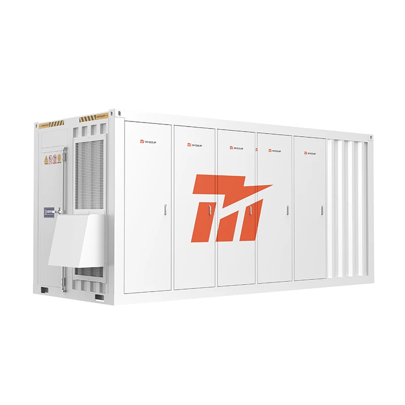
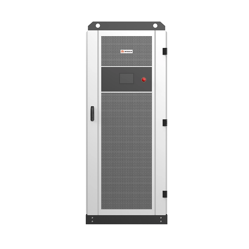
The convergence of these two curves produces a specific engineering answer: a 20-foot, 5 MWh liquid-cooled container energy storage system with grid-forming inverter capability. It is not the largest battery container on the market, nor the cheapest per kilowatt-hour in isolation. It is, however, the smallest commercially deployable unit that simultaneously clears the NOGRR272 compliance threshold and delivers enough energy density to function as a capacity-bypass asset behind the meter. This article examines why that combination matters more in October 2026 than it did twelve months ago, how the physics and the tariff structures interact, and what a technically credible deployment pathway looks like for a Texas C&I site that cannot afford to sit in the interconnection queue.
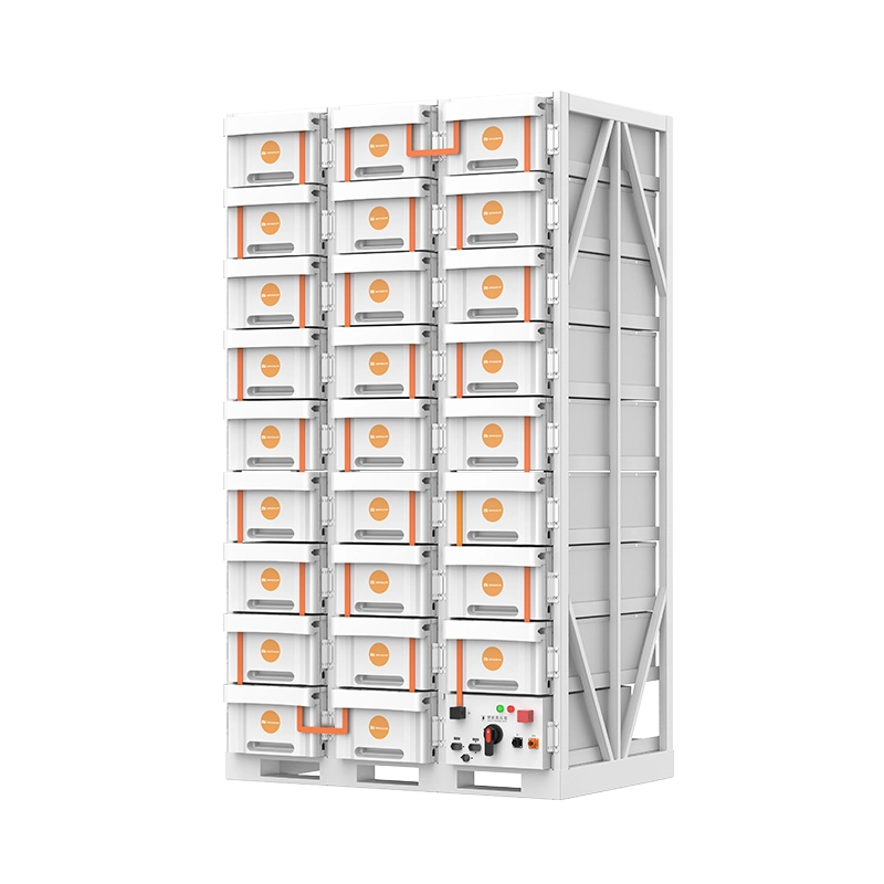
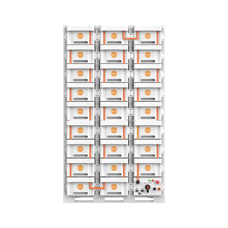
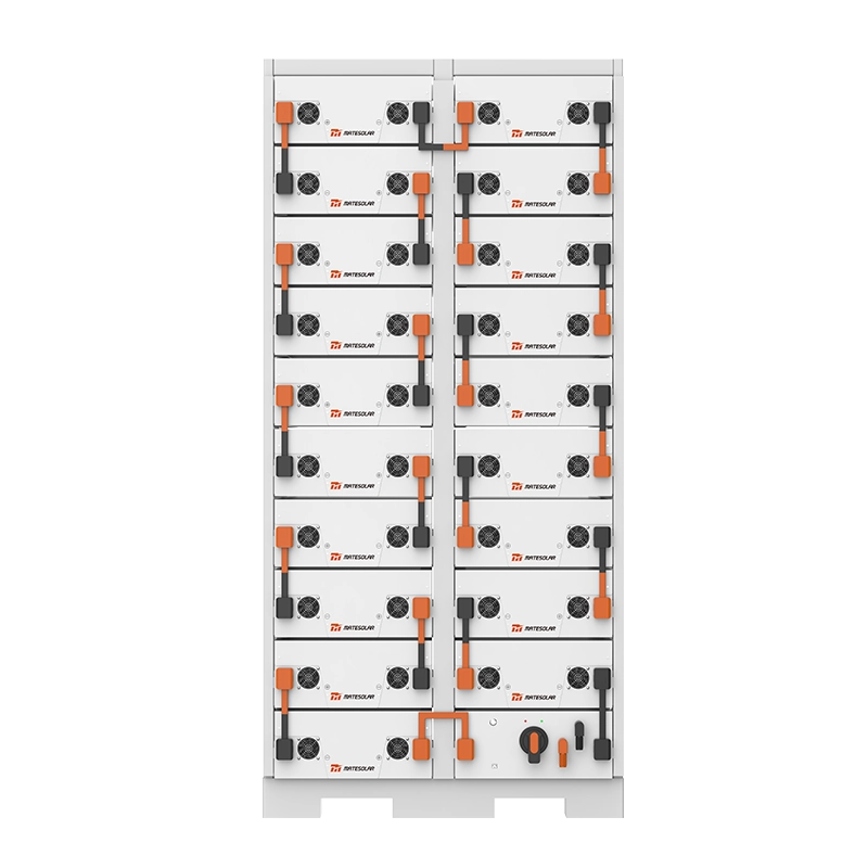
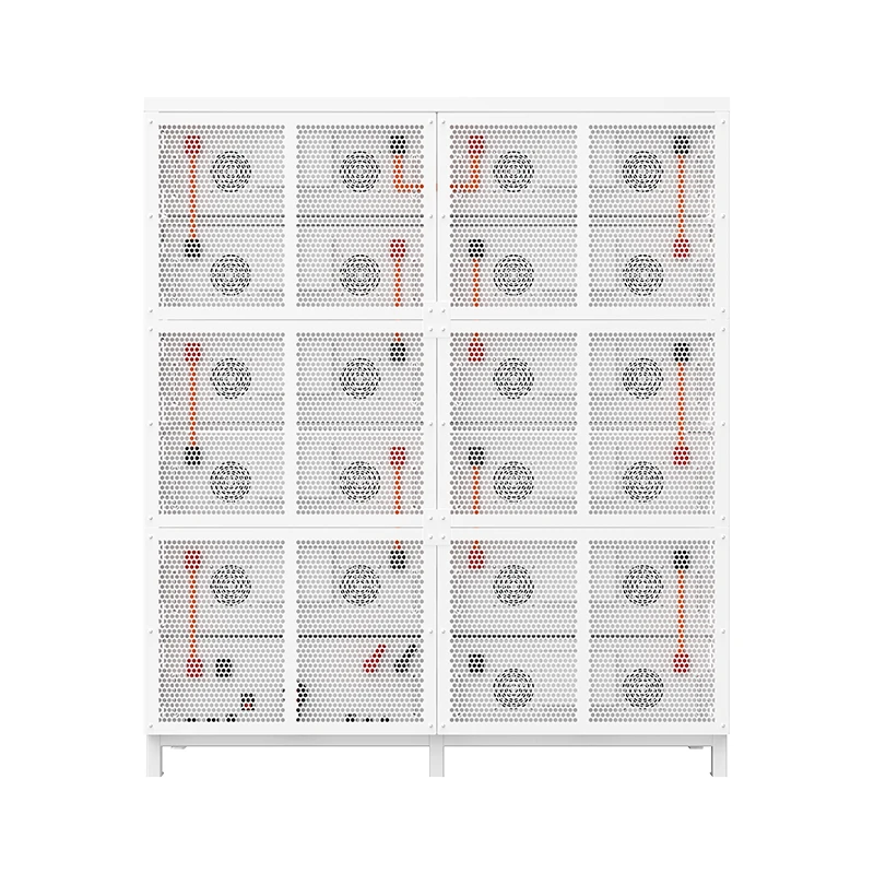
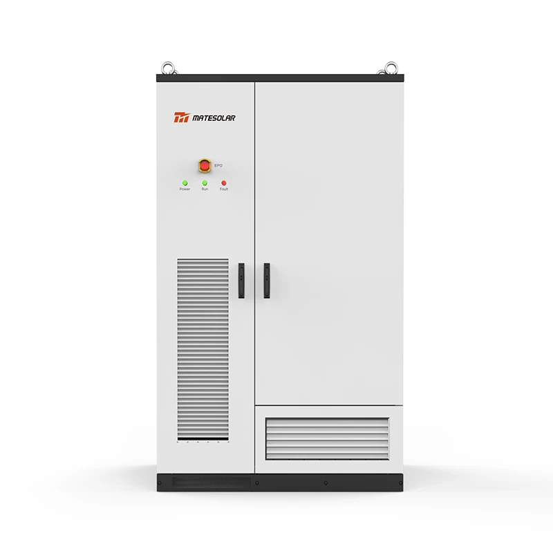
Product reference: The technical specifications and compliance framework discussed in this article map to the 20ft 5MWh Liquid Cooling Container Energy Storage System, a grid-forming-ready AC block detailed on MateSolar’s product page. → View the 20ft 5MWh Liquid Cooling Container Energy Storage System.
1. What “Grid-Forming Admission” Actually Means After April 1, 2026
Before discussing bypass strategies, the compliance baseline must be stated precisely, because a great deal of marketing language in the storage industry uses “grid-forming” loosely. NOGRR272 does not define grid-forming as a marketing category. It defines a set of Advanced Grid Support (AGS) capabilities that an inverter-based ESR must demonstrate under test, and PGRR121 specifies the modeling and model-quality tests through which those capabilities are validated.
1.1 The technical distinction that matters
A conventional grid-following inverter behaves as a controlled current source. It measures the grid voltage waveform, extracts the phase angle through a phase-locked loop, and injects current at a commanded magnitude and angle relative to that measured voltage. When the grid is strong — high short-circuit ratio, abundant synchronous inertia — this works well. When the grid is weak, or when synchronous machines trip and the system frequency derivative (RoCoF) accelerates, the phase-locked loop itself becomes a vulnerability. The inverter can lose synchronism, trip, or interact with other inverters in oscillatory modes that propagate rather than damp.
A grid-forming inverter behaves as a controlled voltage source behind an impedance. It establishes an internal voltage phasor and holds it, adjusting active and reactive power through droop or virtual synchronous machine control rather than following an externally measured angle. ERCOT’s requirement is explicit on this point: the GFM device must “behave like a controlled voltage source, not a conventional controlled current source,” and ERCOT has introduced a test framework — items 5 through 7 in the AGS-ESR test sequence — to verify that behavior under dynamic events. The AGS requirements include the ability to maintain internal voltage phasors and synchronize with the grid during dynamic events, and PGRR121 adds an Inertia Response Test and a Loss of Synchronous Machine Test to the Dynamics Working Group’s Model Quality Test suite.
The practical implication for procurement is that a containerized BESS cannot be “made grid-forming” by a firmware update after delivery unless the power conversion system was designed with that control architecture, the DC-side headroom to provide fault current, and the thermal margin to sustain voltage-source behavior during transients. ERCOT’s IBRWG has noted that, at least in the current rulemaking, the capabilities must be provided within equipment rating — no additional overload capability is mandated — but the equipment must still be capable of short-circuit current contribution on the order of 2.0 per unit of inverter rating to satisfy the emerging GFM consensus. A container that was optimized solely for energy arbitrage at 0.5C may not have the PCS oversizing or the control-loop bandwidth to meet that requirement.
1.2 What happens to a project that misses the threshold
The commercial consequence of non-compliance is not a fine. It is a timeline reset. An ESR that executes its SGIA before April 1, 2026 is grandfathered under the prior framework. An ESR that executes on or after that date must provision AGS capabilities, submit PGRR121-compliant models, and operate in conformance with the test results. If the selected equipment cannot pass the model quality tests, the project does not receive a waiver; it either re-procures the PCS and battery system or it delays its interconnection. In a market where the difference between a 2027 commercial operation date and a 2029 commercial operation date can determine whether a data-center offtake agreement is financeable, that is a binary risk.
ERCOT’s own projections place new inverter-based capacity in excess of 100 GW by 2026, and more than twenty Generic Transmission Constraints have already been implemented to manage reliability risks tied to IBR behavior. The system is not making an academic point about power electronics. It is managing a grid in which synchronous inertia is declining faster than transmission and synchronous condenser additions can compensate. The AGS requirement is the reliability instrument, and the 5 MWh container is the smallest unit through which a C&I developer can acquire a compliant building block.
Table 1 — Grid-Following vs. Grid-Forming ESR: The Compliance Divide Under NOGRR272/PGRR121
| Parámetro | Grid-Following ESR (pre-April 2026 baseline) | Grid-Forming ESR (NOGRR272 / PGRR121 compliant) | Why the difference determines project viability |
| Control reference | Phase-locked loop to measured grid voltage | Internal voltage phasor, droop/VSM control | GFL cannot establish voltage on a weak grid; GFM can |
| Short-circuit current contribution | Typically ≤1.2 p.u., current-limited | Up to 2.0 p.u. of inverter rating expected | Drives PCS semiconductor sizing and DC-link design |
| Inertia response | None; relies on synchronous machines | Synthetic/virtual inertia validated by PGRR121 Inertia Response Test | Directly addresses ERCOT’s declining-inertia reliability gap |
| Loss-of-synchronism behavior | May trip or lose PLL lock | Must maintain synchronism and voltage phasor following loss of synchronous generation | Determines whether the ESR remains online during system disturbances |
| Model validation | Standard positive-sequence models | EMT-compatible models + DWG Model Quality Tests | PGRR121 links compliance to plant-specific models; inaccurate models invite penalties |
| Applicability trigger | SGIA executed before April 1, 2026 | SGIA executed on or after April 1, 2026 | Grandfathering is date-based, not technology-based |
| Commercial consequence of non-compliance | Interconnection may proceed under legacy rules | No SGIA execution without validated AGS capability | A non-compliant container is a stranded asset for new interconnections |
2. The Data-Center Queue and the Economics of Not Waiting
The grid-forming requirement is the gate. The data-center queue is the reason a growing number of C&I developers are choosing not to walk through that gate at all — at least not for their entire load.
2.1 The scale of the queue is not a forecasting exercise
ERCOT’s large-load interconnection queue stands at approximately 474 GW of requests. To put that number in perspective, the record peak demand on the ERCOT system — set during the July 2026 heat wave — exceeded 91 GW. The queue is more than five times the all-time system peak. Roughly 90% of those requests are data centers. ERCOT has completed conditional classifications for 362 large-load requests totaling 191.8 GW, with 204 projects and 66.4 GW eligible for the Batch Zero process.
These are not small numbers with gradual implications. They describe a situation in which the transmission planning process, the generation interconnection process, and the large-load study process are all being asked to absorb a volume of requests that is structurally disconnected from the pace at which physical infrastructure can be built. ERCOT added roughly 23 GW of generation across 2024–2025, with another 9 GW expected in early 2026 — real progress, but an order of magnitude below the queue. The queue is not a pipeline; a substantial portion of it is option-holding rather than committed capital, which is precisely why the state audit was initiated.
2.2 The audit changed the risk profile of queue-dependent projects
On August 3, 2026, Governor Abbott directed the PUCT and ERCOT to conduct a comprehensive verification and audit of every data center advancing through the ERCOT interconnection process, covering five categories of information: whether the project is paying its own way, its projected annual and peak consumption and any effort to construct on-site generation, its water sourcing and cooling technology, its community and property impacts, and the ownership and controlling interests behind the application. ERCOT delayed the Batch Zero process and sought a good-cause exemption from the PUCT. The TCEQ subsequently paused all permit issuance for data-center projects statewide pending completion of the grid audit, now expected in mid-December 2026.
For a project that has already posted $50,000 per MW of financial security — the default Batch Zero requirement for large loads — the audit introduces a delay of indeterminate duration after the security has been committed. Batch Zero itself carries milestones: legacy LLIS approvals by July 10, 2026, project information submission and financial security posting by July 15, and a commitment deadline currently planned for June 2027. A project that slips past those milestones does not simply lose its place in line; it may require a new study cycle under the revised large-load rules.
2.3 “Bypass” is not a single strategy — it is a spectrum of grid-dependency reduction
The phrase “bypassing the capacity upgrade” is used loosely in industry commentary. Technically, there are at least three distinct pathways, and they carry different regulatory treatment.
Pathway A — Behind-the-meter (BTM) generation and storage with a grid-withdrawal limit. ERCOT’s WLPUN (Withdrawal Limit under Planning Guide) framework allows co-located generation and load to operate behind an enforceable grid-withdrawal limit, reducing incremental transmission dependency by netting on-site generation against load. This is not an exemption from the generation-interconnection rules: new generators proposed as part of a WLPUN remain subject to applicable generation-interconnection requirements. But it changes the transmission upgrade obligation, because the net withdrawal at the point of interconnection is lower than the gross load.
Pathway B — Islanded or “grid-independent” operation with a bridging resource. A growing number of Texas data-center developers are deploying behind-the-meter gas and batteries rather than waiting in ERCOT and PJM interconnection lines, and some are structuring the initial phase as an islanded microgrid that later transitions to grid-connected operation when transmission upgrades are completed. A hybrid “gas + storage” bridge has been described in which on-site generation supplies the load directly in the early phase, with grid interconnection added later.
Pathway C — Net-zero or near-net-zero co-location at the point of interconnection. A framework under discussion in ERCOT’s Batch Zero process would allow portions of load to energize ahead of major transmission upgrades where co-located resources offset facility demand at the point of interconnection under normal operating conditions. This is not a permanent bypass; it is a conditional energization pathway that depends on the co-located resource performing reliably.
The 5 MWh liquid-cooled container participates in all three pathways, but its role differs. In Pathway A, it is the fast-ramping netting asset that enforces the withdrawal limit and absorbs the difference between load and on-site generation. In Pathway B, it is the bridging asset that provides ride-through and black-start capability for an islanded data center until the gas turbines or the grid connection is available. In Pathway C, it is the compliance asset that demonstrates to ERCOT that the co-located resource can offset demand during normal operations, which is the condition on which the conditional energization depends.
Table 2 — Three Grid-Dependency Reduction Pathways and the Storage Specification That Each Demands
| Pathway | Regulatory treatment | Primary storage function | Critical specification driver | Typical project scale |
| A: BTM with WLPUN withdrawal limit | Generation interconnection still required; transmission upgrade obligation reduced by netting | Enforce withdrawal limit; shave peaks; absorb on-site generation variability | C-rate and round-trip efficiency; SCADA integration with utility telemetry | 5–50 MWh |
| B: Islanded / bridging microgrid | Initial operation may be off-grid; later transition to grid-connected | Voltage/frequency reference; black-start; ride-through until bridging generation is online | Grid-forming PCS; black-start capability; thermal resilience at high ambient | 20–200 MWh |
| C: Net-zero co-location at POI | Conditional energization ahead of transmission upgrades; subject to ERCOT study | Offset facility demand at POI under normal conditions; demonstrate net-zero performance | Round-trip efficiency; dispatch accuracy; model validation under PGRR121 | 50–500 MWh |
The strategic insight is that the 5 MWh container is not competing with utility-scale 4-hour systems on a dollar-per-megawatt-hour basis in these applications. It is competing with time: the difference between a facility that energizes in 2027 and one that energizes in 2030. When the cost of delay is measured in lost revenue from a hyperscale tenant or in the carrying cost of an unenergized shell, the economic comparison shifts from LCOS to cost of deferred energization.
3. Why 5 MWh in a 20-Foot Footprint Is the Relevant Unit of Analysis
A 20-foot container that holds 5 MWh is not simply a denser version of a 40-foot 3.72 MWh container. The shift from 280 Ah to 314 Ah LFP cells, combined with a 1P104S or 12P416S architecture and liquid cooling, changes the system-level engineering in ways that matter specifically for the two-curve problem described above.
3.1 Energy density and the footprint constraint at C&I sites
Most C&I sites in Texas — manufacturing facilities, logistics hubs, industrial parks, and edge data centers — are not greenfield utility-scale sites with hundreds of acres available. They have constrained laydown areas, existing switchgear, and limited space for fire-rated separation. A 20-foot container with 5,015.96 kWh nominal energy, operating at 0.5P charge/discharge, delivers a nameplate 2.5 MW power rating within a physical footprint of approximately 6,058 × 2,438 × 2,896 mm and a weight under 45,000 kg. That energy density — roughly 117 Wh/l — is approximately 46% higher than a standard 280 Ah-based system at 80 Wh/l.
The practical consequence is that a site can stack four containers on a single PCS and reach 20 MWh of storage within a footprint that would previously have required six or more 40-foot containers of lower-density chemistry. For a data-center campus trying to reduce its grid withdrawal without acquiring additional land, or for an industrial facility with a fixed fence line, that footprint compression is not a convenience. It is the difference between a feasible project and a site-plan rejection.
3.2 Liquid cooling as a grid-forming enabler, not just a density enabler
The thermal management system is often discussed in the context of cell life and round-trip efficiency. Those are important, but they are not the only reason liquid cooling matters in a grid-forming application. A grid-forming PCS operates as a voltage source and must sustain reactive current and fault-current contribution during transients. Those transients produce losses in the PCS and in the battery DC path that are not present during steady-state energy arbitrage. A container that is thermally sized only for 0.5C continuous charge/discharge may not have the cooling headroom to sustain repeated grid-forming events at high ambient temperature without derating.
The 5 MWh liquid-cooled architecture addresses this at the pack level: the coolant loop maintains cell temperature uniformity across the 1P104S or 12P416S configuration, which reduces the risk of localized hotspots during high-current transients. The auxiliary power consumption of the cooling system — on the order of 38 kW for cooling/heating and up to 40 kW continuous including HVAC — is a real parasitic load that must be included in the round-trip efficiency and LCOS calculation. But that parasitic load is the cost of maintaining the thermal margin that grid-forming operation requires. An air-cooled container that claims a lower auxiliary load may be achieving that number by sacrificing the thermal headroom that the AGS tests will demand.
3.3 Round-trip efficiency in the range that matters for demand-charge management
The published round-trip efficiency of 20-foot 5 MWh liquid-cooled containers sits in the 93.5%–94% range, with some configurations claiming >94% and others specifying 94%–95% depending on the C-rate and boundary conditions. In a Texas C&I application where the primary revenue stream is demand-charge reduction and 4CP transmission-cost avoidance, a one-percentage-point difference in RTE is not a rounding error. It translates directly into fewer discharged kilowatt-hours per stored kilowatt-hour, which affects the number of containers required to achieve a given peak-shaving depth.
But the more important efficiency metric for the grid-forming and bypass use cases is cycle-to-cycle consistency under partial state of charge. A data-center bypass asset is not cycling from 0% to 100% every day. It is sitting at a partial state of charge, absorbing or injecting power in response to load fluctuations and grid conditions, and occasionally executing a deep discharge during a grid event or a peak-demand window. The liquid-cooled architecture’s ability to maintain cell balance and temperature uniformity across that duty cycle is what preserves usable capacity over the asset life. A container that achieves 94% RTE in a laboratory full-cycle test but loses 3% of usable capacity per year to thermal imbalance is not delivering 94% in the field.
Table 3 — Nameplate and Operational Specifications: 20ft 5MWh Liquid-Cooled Container (Representative Configuration)
| Parámetro | Valor | Relevance to Texas grid-forming / bypass application |
| Energía nominal | 5,015.96 kWh | Smallest unit that reaches 5 MWh in a 20ft footprint; four units = 20 MWh on one PCS |
| Nominal charge/discharge rate | 0.5P / 0.5P (2.5 MW) | Matches C&I demand-charge windows without oversizing PCS |
| Eficacia de ida y vuelta | 93.5%–94% (published range) | Determines discharged kWh per stored kWh; directly affects demand-charge savings |
| Química celular | LFP 314 Ah prismatic | Thermal stability and cycle life; UL 9540A / NFPA 855 compliance pathway |
| Configuración | 1P104S or 12P416S | Pack-level architecture affects thermal uniformity and BMS granularity |
| Refrigeración | Liquid cooling, active thermal management | Sustains grid-forming transient thermal margin; enables 117 Wh/l density |
| Auxiliary consumption | ~38 kW cooling/heating; ~40 kW continuous incl. HVAC | Must be included in LCOS and round-trip efficiency calculation |
| Temperatura de funcionamiento | −30 °C to 55 °C | Covers Texas summer ambient extremes; derating curves must be checked above 45 °C |
| Clasificación de protección | IP55 | Suitable for outdoor C&I installation with appropriate civil works |
| Dimensions / weight | ~6,058 × 2,438 × 2,896 mm; <45,000 kg | Standard 20ft ISO footprint; transport and foundation design implications |
| Compliance references | IEC 62619, IEC 62477, IEC 63056, UL 1973, UL 9540A, NFPA 855, UN 38.3 | UL 9540A and NFPA 855 are the relevant fire-safety references for Texas AHJ approval |
4. The Economic Layer: LCOS, Demand Charges, and the Cost of Queue Delay
The technical case for a grid-forming 5 MWh container is necessary but not sufficient. A C&I developer or industrial facility will allocate capital only if the economics clear the hurdle rate under a realistic Texas revenue stack. That stack in 2026 is materially different from the 2022–2023 arbitrage-driven model.
4.1 The revenue stack has compressed — and that changes the asset sizing logic
The Texas storage revenue stack has undergone a reset. The arbitrage returns that financed the first wave of utility-scale storage have compressed, and project pro formas are increasingly underwritten on demand-charge savings, capacity value, and resilience rather than on energy arbitrage alone. For a C&I asset, this is not a disadvantage. Demand charges can account for up to 70% of a commercial electricity bill in Texas, and 4CP transmission charges are a separate, significant component. A battery that discharges during the 4CP windows and during the facility’s monthly peak-demand interval can reduce transmission charges by 20%–40%, and one San Antonio manufacturer reduced monthly demand charges by nearly 40% simply by automating battery discharge during peak afternoon heatwaves.
The grid-forming capability adds a second revenue or cost-avoidance layer that is often omitted from C&I pro formas: it makes the asset eligible for interconnection under the post-April 2026 framework y it enables participation in ancillary services or grid-support programs where the asset is front-of-meter. ERCOT’s AGS requirements are not an incentive program; they are a mandate. But an asset that meets the mandate is also an asset that can provide fast frequency response and voltage support, and those capabilities have value in a grid with declining inertia and more than twenty active transmission constraints.
4.2 A defensible LCOS range and the assumptions that drive it
LCOS is a useful comparison metric only if the boundary conditions are stated. Published 2026 estimates for utility-scale lithium-ion storage place LCOS in the $65/MWh** range, with some analyses citing **$46/MWh undiscounted for favorable duty cycles and $65–$70/MWh when incorporating higher augmentation and financing costs. For C&I-scale 5 MWh containers, a well-designed system can achieve an LCOS in the $0.05–$0.08 per kWh range for 2-hour applications, depending on cycle count, augmentation strategy, and the cost of capital.
Those numbers are sensitive to three variables that are specific to the grid-forming and bypass use cases:
Cycle depth and frequency. A demand-charge-focused asset may cycle once per day at partial depth, plus occasional deeper discharges during grid events. A bypass asset in an islanded microgrid may cycle more frequently and at higher C-rates during transients. The LCOS calculation must use the actual duty cycle, not a standard 1-cycle-per-day assumption.
Auxiliary load. The ~40 kW continuous auxiliary load of a liquid-cooled container is a real energy cost. At 2.5 MW discharge, a 40 kW auxiliary load is 1.6% of rated power. Over a year of daily operation, that parasitic load compounds. A rigorous LCOS model includes it.
Augmentation timing. LFP cells in a liquid-cooled container may retain 70% end-of-life capacity after more than 6,000 cycles at 25 °C, but the actual augmentation schedule depends on the depth of discharge and the ambient temperature profile. A container deployed in Houston or San Antonio faces a higher average ambient temperature than one in Amarillo, and the thermal management system’s auxiliary load will be higher as a result.
Table 4 — Illustrative LCOS Sensitivity: 5 MWh Liquid-Cooled Container in a Texas C&I Duty Cycle
| Variable | Low case | Base case | High case | Effect on LCOS |
| Daily cycles (equivalent full cycles) | 0.7 | 1.0 | 1.5 | Linear reduction in $/MWh as cycles increase, until augmentation accelerates |
| Average auxiliary load (kW) | 30 | 40 | 50 | Each 10 kW ≈ 0.4% of rated power; adds $1–$2/MWh at base throughput |
| Eficacia de ida y vuelta | 95% | 94% | 93% | 1 pp RTE reduction ≈ 1.06% more charge energy per discharged MWh |
| Augmentation trigger (% capacity loss) | 20% | 25% | 30% | Earlier augmentation increases capital cost but preserves usable energy |
| Cost of capital (weighted) | 6% | 8% | 10% | LCOS is highly sensitive to discount rate over a 15–20 year life |
| Indicative LCOS range ($/MWh, 2-hour) | ~$46–$55 | ~$55–$70 | ~$70–$85 | Must be compared on the same boundary conditions, not as a single headline number |
The LCOS comparison is not the decisive factor in a bypass decision. The decisive comparison is between the LCOS of the storage asset and the cost of the transmission upgrade plus the revenue loss from the queue delay. For a data-center project with a 300 MW load, the transmission upgrade cost can be in the tens of millions of dollars, and the carrying cost of a 24–36 month delay can exceed the entire capital cost of a 20–50 MWh BTM storage system. That is the economic framing in which a 5 MWh container becomes a rational first purchase rather than a discretionary efficiency investment.
5. Deployment Reality: What a Compliant, Maintainable System Requires in Texas
A technically excellent container that cannot be commissioned, maintained, and kept in compliance is a liability. The Texas C&I storage market has a specific deployment profile: sites are distributed, skilled labor is concentrated in metropolitan areas, and the owner’s engineering team is often remote from the asset. The service model must match that reality.
5.1 Commissioning and grid-forming validation
Commissioning a grid-forming ESR under NOGRR272 is not a plug-and-play process. The PCS must be parameterized for the site’s short-circuit ratio, the protection coordination must be verified, and the PGRR121 model must be validated against the as-built configuration. The Inertia Response Test and Loss of Synchronous Machine Test require test equipment and engineering support that a typical electrical contractor does not carry. For a C&I site, the practical approach is to have the equipment supplier provide the commissioning protocol, the validated models, and remote engineering support during the test, with a specialist commissioning engineer on site for the grid-forming validation if the project scale justifies it.
For smaller C&I projects, remote commissioning support is often sufficient for the mechanical and electrical checks, with the grid-forming test witnessed by the utility or ERCOT-designated entity. The key requirement is that the supplier’s engineering team has already validated the PCS against the AGS test framework on a test bench or at a reference site. A container that has not been through that validation places the commissioning risk on the customer’s schedule.
5.2 Service model for distributed C&I assets
The Texas C&I market includes many sites that are hundreds of miles from the nearest major service center. A service model that assumes a local installation crew and a local maintenance technician is not compatible with that geography. The realistic model has three tiers:
Tier 1 — Hardware quality issues. If a module, BMS board, coolant pump, or PCS component fails within the warranty period, the supplier ships the replacement part with installation instructions and provides remote technical guidance for the swap. The site’s existing electrical contractor or maintenance team performs the physical replacement. If the failure is severe enough to require a full container replacement, the supplier manages the return and replacement logistics.
Tier 2 — Software and controls issues. Firmware updates, BMS communication faults, SCADA integration problems, and dispatch-algorithm tuning are handled remotely. The supplier’s technical team accesses the system through a secure remote connection, diagnoses the issue, and either resolves it directly or provides step-by-step guidance to on-site personnel.
Tier 3 — Large project commissioning and complex integration. For large C&I or multi-container projects where the grid-forming validation, protection coordination, or microgrid transition logic is complex, the supplier can arrange for a technical engineer to travel to the site for commissioning and integration support. This is project-specific and should be scoped in the supply agreement rather than assumed as a standard service.
This model is not a limitation; it is a deliberate allocation of engineering resources to the tasks that require physical presence and remote resolution to the tasks that do not. A grid-forming container that has been factory-validated and is supported by a remote engineering team can be maintained across a distributed Texas fleet without a dedicated local service footprint.
5.3 Spare-parts strategy and coolant-loop maintenance
The liquid-cooling loop is the component that most distinguishes a 5 MWh container from an air-cooled system in terms of maintenance. Coolant quality, pump health, and heat-exchanger fouling must be monitored. The BMS and thermal management system should expose coolant temperature differentials, pump runtime, and pressure data to the remote monitoring platform so that degradation is detected before it derates the system. A spare coolant pump, a set of quick-disconnect fittings, and a coolant top-up kit are the minimum critical spares for a distributed fleet. The supplier should provide a recommended spares list with the commissioning documentation, and the remote monitoring platform should generate a maintenance alert when the coolant delta-T exceeds a configured threshold.
5.4 Fire-safety and AHJ approval
UL 9540A cell-level and module-level test data, combined with NFPA 855 compliance documentation, is the baseline for Texas AHJ approval. The 20-foot footprint and liquid-cooled architecture do not eliminate the need for separation distances or fire-water access, but the documented test data reduces the probability of a prolonged plan review. The supplier should provide the UL 9540A report summary, the NFPA 855 compliance matrix, and a site-layout template that the customer’s engineer of record can adapt to local setback requirements.
Table 5 — Deployment and Service Responsibility Matrix for a Distributed Texas C&I Fleet
| Activity | Supplier responsibility | Customer / local contractor responsibility | Remote vs. on-site |
| Factory validation of grid-forming PCS | Provide AGS test report and PGRR121-compatible models | Review and accept model package | Remote |
| Mechanical and electrical installation | Provide installation manual and torque/coolant specifications | Perform physical installation and connection | On-site (customer) |
| Commissioning — power-on and basic checks | Remote guidance; provide checklist | Execute checklist with local electrician | Remote guidance |
| Grid-forming validation test | Provide test protocol and engineering support | Coordinate with utility/ERCOT witness; provide site access | Remote or on-site depending on project scale |
| Hardware warranty replacement | Ship part; provide swap instructions; manage RMA | Perform physical swap | Remote guidance; on-site execution by customer |
| Software/firmware issue | Diagnose and resolve remotely; push update | Provide network access and site contact | Remote |
| Coolant-loop maintenance | Provide procedure and spares; monitor data | Perform periodic inspection and top-up | Remote monitoring; on-site execution |
| Large-project commissioning | Provide on-site technical engineer (scoped per project) | Provide site logistics and local coordination | On-site (supplier, project-specific) |
6. Competitive Positioning: What the 5 MWh Container Is — and Is Not
The Texas C&I storage market includes several credible alternatives, and a technically honest article must position the 5 MWh liquid-cooled container against them without overstating its role.
6.1 Versus larger utility-scale containers
A 5 MWh container is not a substitute for a 20 MWh or larger utility-scale BESS in a front-of-meter arbitrage or ancillary-services project. Those projects benefit from economies of scale in PCS, transformer, and balance-of-plant costs that a 5 MWh unit cannot match on a dollar-per-MWh basis. The 5 MWh container’s advantage is in distributed, behind-the-meter, and space-constrained applications where the project scale is determined by the load, not by the transmission interconnection capacity.
6.2 Versus air-cooled C&I cabinets
Air-cooled C&I cabinets in the 100 kWh to 1 MWh range are simpler to install and may have lower auxiliary power consumption in mild climates. But they generally cannot provide grid-forming capability at the 2.5 MW scale within a single enclosure, and their energy density is lower. For a site that needs to enforce a withdrawal limit of several megawatts or provide black-start capability for a data-center hall, the 5 MWh liquid-cooled container is the smallest unit that meets the functional requirement without paralleling dozens of small cabinets.
6.3 Versus Tesla Megapack and other integrated utility-scale products
Tesla’s Megapack 2 XL has been widely deployed in ERCOT, including the 300 MW Bocanova project that came online in 2026. Megapack is a proven, integrated product with a mature grid-forming control architecture. The 5 MWh liquid-cooled container competes on procurement flexibility, container-level granularity, and the ability to right-size a BTM asset without committing to a utility-scale block. A C&I developer that needs 20 MWh does not necessarily want to procure a 20 MWh Megapack block if the site layout, interconnection limit, or phased deployment schedule favors four independently dispatchable 5 MWh containers. The competitive question is not “which product is better in the abstract” but “which unit of decomposition matches the project’s interconnection and load profile.”
7. Frequently Asked Questions
Q1: Does a 5 MWh container with a grid-forming PCS automatically satisfy NOGRR272?
No. NOGRR272 compliance is demonstrated through the PGRR121 model quality tests and the AGS-ESR test framework, not through a product datasheet claim. The PCS must be capable of voltage-source behavior and the required short-circuit current contribution, and the plant-specific model must pass the Inertia Response Test and Loss of Synchronous Machine Test. A container that is marketed as “grid-forming-ready” but has not been validated against the ERCOT test sequence may require re-parameterization, additional hardware, or replacement before it can execute an SGIA on or after April 1, 2026.
Q2: If my SGIA was executed before April 1, 2026, can I still use a grid-following container?
The NOGRR272 requirements apply to ESRs with an original SGIA executed on or after April 1, 2026. If the SGIA was executed before that date, the project is not subject to the new AGS requirement under the current rule language. However, the commercial and operational landscape may still favor grid-forming equipment because of its ability to provide grid support and because future rule revisions could extend requirements to existing resources. The decision should be made with counsel and with the interconnecting utility’s confirmation of the applicable rule set.
Q3: How many 5 MWh containers does a data center need to “bypass” a transmission upgrade?
There is no universal number. The sizing depends on the net withdrawal limit that the transmission provider will accept, the load profile of the facility, the capacity of any on-site generation, and the duration for which the storage must sustain the withdrawal limit during grid events or peak-load periods. A 5 MWh container with 2.5 MW discharge can offset 2.5 MW of load for two hours at full depth. A 30 MW data-center hall seeking to reduce its peak withdrawal by 10 MW for four hours would require a substantially larger storage fleet, potentially on the order of 20–40 MWh or more, depending on the generation mix. The sizing must be engineered against the specific WLPUN or co-location framework, not extrapolated from a rule of thumb.
Q4: Is liquid cooling a disadvantage in Texas because of the auxiliary power load?
Liquid cooling consumes more auxiliary power than air cooling in some operating regimes, and that parasitic load must be included in the round-trip efficiency and LCOS calculation. The countervailing benefit is thermal stability at high ambient temperature and the ability to sustain grid-forming transients without derating. In a Texas summer, an air-cooled system may derate precisely when the grid needs the storage most; a liquid-cooled system with adequate thermal margin is more likely to deliver nameplate power during those events. The auxiliary load is the cost of that delivered capacity, and it should be evaluated on a net-delivered-MWh basis rather than on a gross-RTE basis alone.
Q5: What happens if a container fails in the field and there is no local service team?
The service model is tiered. Hardware quality issues are addressed through part shipment with installation instructions and remote guidance, or through full container replacement for severe failures. Software and controls issues are resolved remotely. Large project commissioning can include an on-site technical engineer when the project scope requires it. The customer’s electrical contractor or maintenance team performs the physical swap, and the supplier’s engineering team supports the diagnosis and verification. This model is designed for distributed C&I fleets where a dedicated local service footprint is not economically justified for every site.
Q6: Can a 5 MWh container participate in ERCOT ancillary services if it is behind the meter?
Participation in ERCOT ancillary services requires the resource to be registered and to meet the market’s telemetry, dispatch, and performance requirements. A behind-the-meter asset may participate through an aggregator or through a qualified scheduling entity, subject to the applicable ERCOT protocols. The grid-forming capability improves the asset’s technical ability to provide fast frequency response and voltage support, but market participation is a separate commercial and registration decision. The asset’s controls must be configured to prioritize the site’s load-serving obligation before exporting or providing ancillary services, and the dispatch logic must be agreed with the site owner and the aggregator.
Q7: Does the Texas data-center audit mean no new data centers will be approved in 2026?
The audit has paused the Batch Zero review process and the TCEQ permit issuance for data-center projects pending completion, now expected in mid-December 2026. It does not permanently prohibit new data centers. Projects that demonstrate compliance with the audit criteria — including on-site generation or demand-reduction measures, water stewardship, and financial standing — can proceed once the audit is complete and the PUCT/ERCOT process resumes. The practical effect is a timeline delay, not a categorical denial, but the delay is material for projects with near-term offtake obligations.
Q8: Is a 5 MWh container large enough to support black-start for a data center?
Black-start capability depends on the critical load that must be energized first, the inrush current of the downstream transformers and motors, and the duration for which the storage must sustain the island before additional generation is synchronized. A single 5 MWh container with grid-forming capability can provide a voltage and frequency reference for a partial black-start sequence — for example, energizing the control systems, cooling plant, and a portion of the IT load — but a full data-center hall with megawatt-scale chillers and UPS systems typically requires a larger storage fleet or a hybrid storage-plus-generation architecture. The black-start scope must be defined in the system study, not assumed from the container’s nameplate energy.
Q9: What is the expected cycle life of a 5 MWh liquid-cooled container in a Texas C&I duty cycle?
Published cycle-life figures for 314 Ah LFP cells in liquid-cooled containers cite more than 6,000 cycles to 70% end-of-life at 25 °C. The actual cycle life in a Texas installation depends on the average state of charge, depth of discharge, ambient temperature profile, and the thermal management system’s ability to maintain cell temperature uniformity. A conservative procurement specification should require the supplier to provide a cycle-life warranty tied to a defined duty cycle and ambient temperature envelope, and the LCOS model should use that warranted cycle life rather than the laboratory maximum.
Q10: Can the container be shipped and installed as a single unit, or does it require on-site assembly?
The 20-foot container is factory-assembled and pre-tested to minimize on-site labor. The container arrives with the battery modules, BMS, thermal management system, and fire-protection system installed. On-site work is limited to foundation placement, electrical connection to the PCS and switchgear, coolant commissioning (if the coolant is shipped separately for transport safety), and communication/SCADA integration. The degree of on-site work depends on whether the PCS is integrated into the container or supplied as a separate skid, and on the site’s interconnection configuration.
8. The Practical Decision Framework for Q4 2026
A Texas C&I developer or industrial facility facing the two-curve problem should structure the procurement decision around four questions, in this order:
First, does the project require a new SGIA on or after April 1, 2026? If yes, grid-forming capability is not optional. The equipment selection must start with the PCS control architecture and the PGRR121 model validation, not with the battery price per kilowatt-hour.
Second, what is the cost of queue delay relative to the cost of a BTM storage fleet? If the project’s revenue or carrying cost is highly sensitive to energization date, the economic comparison should be made on a deferred-energization basis, not on a standalone LCOS basis. The storage asset’s value includes the revenue that is preserved by not waiting.
Third, what is the net withdrawal limit that the transmission provider will accept, and what storage duration is required to enforce it? The 5 MWh / 2.5 MW container is a building block. The number of blocks is determined by the load profile, the on-site generation capacity, and the duration of the peak-shaving or netting window.
Fourth, what service model is realistic for the site’s geography and staffing? A distributed Texas fleet requires a remote-capable service model with factory-validated equipment, a spares strategy, and a clear escalation path for complex commissioning. The supplier’s ability to support the asset remotely is as important as the asset’s nameplate specifications.
The 20-foot 5 MWh liquid-cooled container is not a universal answer to every Texas storage question. It is a specific answer to a specific problem: how to acquire grid-forming compliance and capacity-bypass capability in the smallest commercially viable unit, without committing to a utility-scale block that exceeds the site’s load or its interconnection limit. In a market where the queue is measured in hundreds of gigawatts and the compliance deadline has already passed for new interconnections, that specificity is the point.
MateSolar — One-Stop PV & Energy Storage Solutions Provider. From grid-forming-ready 20ft 5MWh liquid-cooled containers to project-level engineering and remote technical support, MateSolar supports C&I and data-center projects across Texas and ERCOT with equipment, modeling, and commissioning guidance tailored to the post-NOGRR272 interconnection landscape.