


Driven by rising electricity costs, grid reliability challenges, and global decarbonization goals, commercial and industrial (C&I) solar-plus-storage has become one of the fastest-growing segments in the renewable energy industry. Across North America, Europe, Central America, and Latin America, businesses, industrial parks, mining operations, and commercial facilities are increasingly investing in on-site energy storage to cut utility bills, protect against power outages, and maximize the value of on-site solar generation. In Europe, volatile wholesale electricity prices and strict decarbonization targets have further accelerated adoption, with commercial storage deployments growing over 50% year-over-year across key markets like Germany, Spain, and Italy.
Among all standardized C&I storage configurations, the 1MW / 2MWh system has emerged as the industry workhorse. Its 0.5C charge/discharge rate aligns perfectly with typical 2-hour peak demand windows and time-of-use rate structures, while its modular, containerized design enables fast deployment, predictable costs, and scalability for facilities of many sizes.
This guide breaks down everything project stakeholders need to know about 1MW/2MWh solar energy storage systems: core design considerations, detailed component breakdowns, validated product solutions, and an in-depth comparison of grid-tied, off-grid, and hybrid architectures. Whether your priority is financial return, uninterrupted power supply, or energy independence, this analysis will help you identify the right solution for your operation.
1. Key Pre-Design Factors for Every Project
A properly sized solar-plus-storage system depends on far more than just the facility’s total energy use. Local solar resources, available installation space, grid conditions, and the customer’s core objectives all shape the final system design and financial performance.
1.1 Peak Sun Hours: The Foundation of Solar Yield
Peak Sun Hours (PSH) measures the total daily solar irradiance at a location, converted into equivalent hours of standard 1000 W/m² sunlight. This single number directly determines how much energy a 1MW solar array will generate each day, and therefore how well it pairs with a 2MWh battery bank.
Daily energy production can be estimated with a simple formula:
Daily PV Generation = Installed PV Capacity (kWp) × Daily Peak Sun Hours × System Efficiency Factor
A typical commercial solar system has an overall efficiency factor of 0.78 to 0.85, accounting for temperature losses, soiling, inverter efficiency, wiring losses, and component mismatch.
Typical PSH Values Across Target Markets
| Región | Average Daily Peak Sun Hours | Solar Resource Classification |
| Northern Mexico, Southwest US | 5.5 – 6.5 hours | Excelente |
| Central America, Caribbean islands | 5.0 – 6.0 hours | Very good |
| Southern Europe (Spain, Italy, Greece) | 4.5 – 5.5 hours | Bien |
| Southern South America, Central Mexico | 4.5 – 5.5 hours | Bien |
| Southeast US, coastal Latin America | 4.0 – 5.0 hours | Moderado |
| Northern / Central Europe (Germany, UK, France) | 3.0 – 4.0 hours | Fair |
| Higher-latitude southern regions | 3.0 – 4.0 hours | Fair |
How PSH Impacts a 1MW/2MWh System
- High-solar regions (PSH > 5.5h): A 1MW array produces 4300–5500 kWh per day, more than enough to fully charge a 2MWh battery. The battery is primarily used to shift midday excess solar to evening peak hours, smooth solar output fluctuations, and export surplus energy when allowed.
- Moderate-solar regions (PSH 4.0–5.5h): A 1MW array produces 3100–4300 kWh per day, which matches very well with a 2MWh battery. The system can charge from midday solar and top up from the grid during off-peak hours for maximum arbitrage value.
- Lower-solar regions (PSH < 4.0h): Solar generation alone cannot fully charge the battery on most days. The battery relies mostly on grid off-peak charging for time-of-use arbitrage, with solar acting as a supplementary cost-reduction measure. In Central and Northern European markets, this dynamic makes grid arbitrage the primary revenue stream for most C&I storage projects.
1.2 Installation Space Requirements
Available roof or ground space is a hard constraint for every project. PV arrays and battery storage have very different footprint requirements, and both must account for access, setbacks, and safety clearances.
1MW PV Array Footprint
Based on modern 550W monocrystalline modules (approx. 2.58 m² each), a 1MW array requires roughly 1820 modules with a pure panel area of about 4700 m². Actual installed area is significantly larger due to spacing, setbacks, and obstructions.
| Installation Type | Typical Power Density | Total Area Required for 1MW |
| Low-slope metal roof (near-flush mount) | 100 – 120 W/m² | 8,300 – 10,000 m² |
| Flat concrete roof (tilted racking) | 70 – 90 W/m² | 11,000 – 14,300 m² |
| Ground-mount (optimal tilt, single-axis tracker) | 60 – 80 W/m² | 12,500 – 16,700 m² |
Note: Roof installations must also deduct 15–25% of gross area for skylights, vents, HVAC units, fire access paths, and shading obstructions.
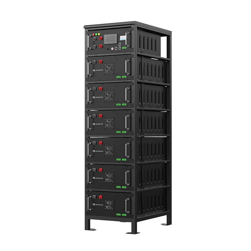
2MWh Battery Storage System Footprint
Most 1MW/2MWh C&I storage systems are delivered as pre-assembled outdoor cabinets or standard containerized units. Modular cabinet-based designs require less total space than full container systems and offer greater layout flexibility for crowded urban or industrial sites.
| Configuración | Unit Dimensions | Base Footprint per Unit | Total Required Area for 2MWh (with access & safety clearances) |
| Modular liquid-cooled outdoor cabinets | 1.2m × 1.0m × 2.2m per unit | ~1.2 m² | 25 – 35 m² |
| Standard 40ft air-cooled container | 12.19m × 2.44m | ~29.8 m² | 50 – 65 m² |
All battery installations must comply with local fire codes, including required setbacks from buildings, transformers, and combustible materials, plus dedicated fire service access.
1.3 Additional Environmental & Electrical Constraints
- Ambient temperature range: High-temperature climates require liquid cooling systems; cold climates require integrated battery heating. Liquid cooling is strongly recommended for most markets across Latin America, the Southern US, and Southern Europe.
- Altitude: Equipment must be derated above 2000m elevation; transformers and PCS units require special selection.
- Corrosive environments: Coastal and industrial sites require upgraded corrosion protection and higher IP ratings.
- Grid interconnection limits: Local utility rules on maximum export capacity, anti-islanding requirements, and voltage level directly determine PCS specifications and system architecture. Standards vary by region: IEEE 1547 in North America, EN 50549 in Europe, and IEC-based local standards in Latin America.
- Load profile: The shape of the facility’s daily load curve, peak demand, power factor requirements, and harmonic sensitivity define the optimal operating strategy and battery sizing.
2. Core System Configuration of a 1MW/2MWh Solar-Plus-Storage System
A complete solar-plus-storage installation consists of five major subsystems working together: the PV generation array, battery energy storage bank, power conversion system, energy management system, and auxiliary support systems.
2.1 PV Generation Subsystem
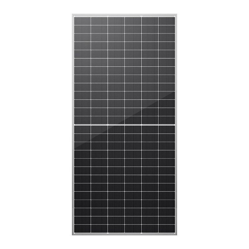
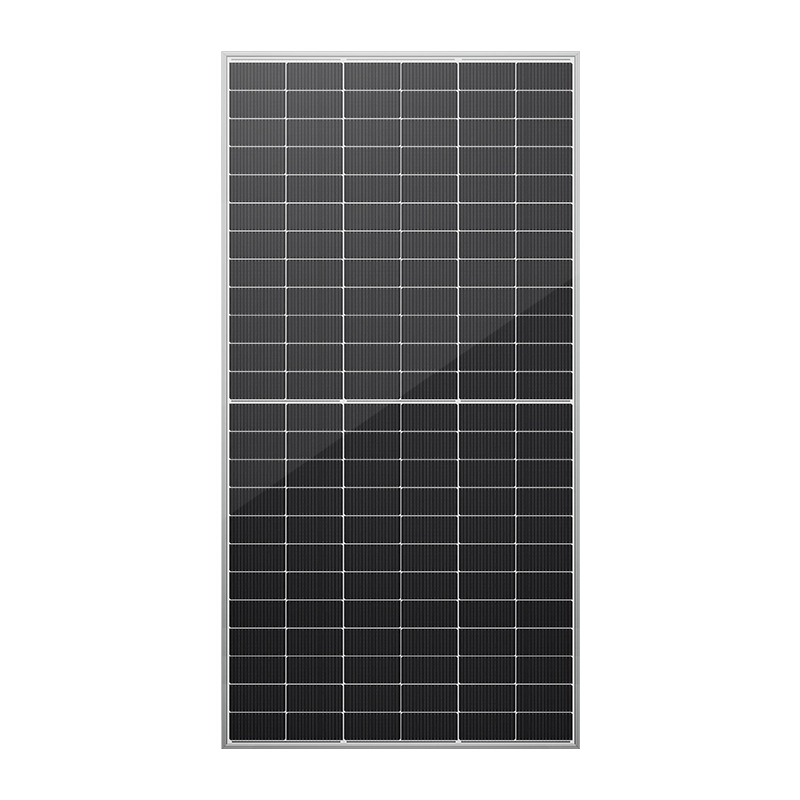
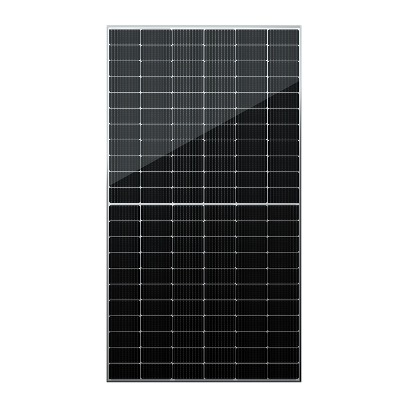
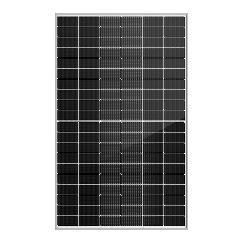
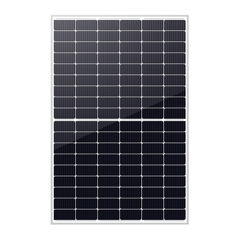
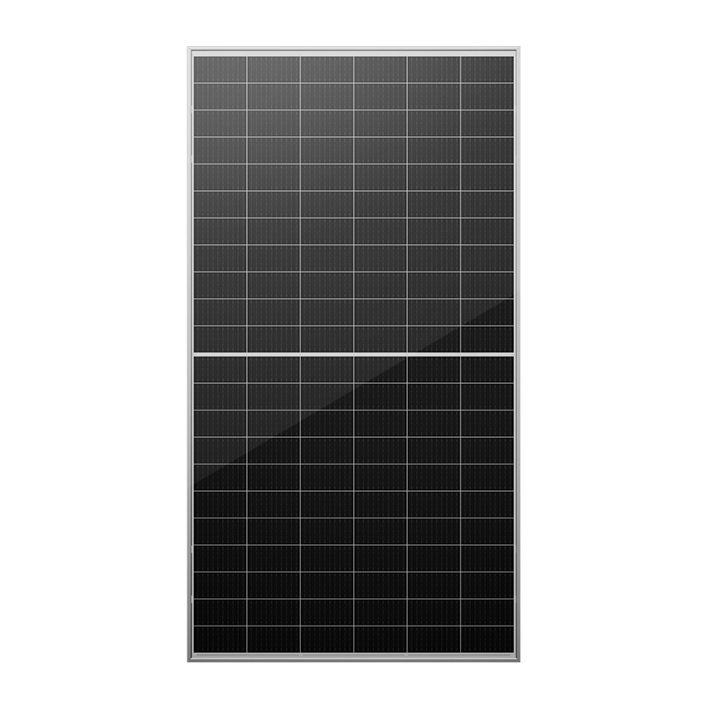
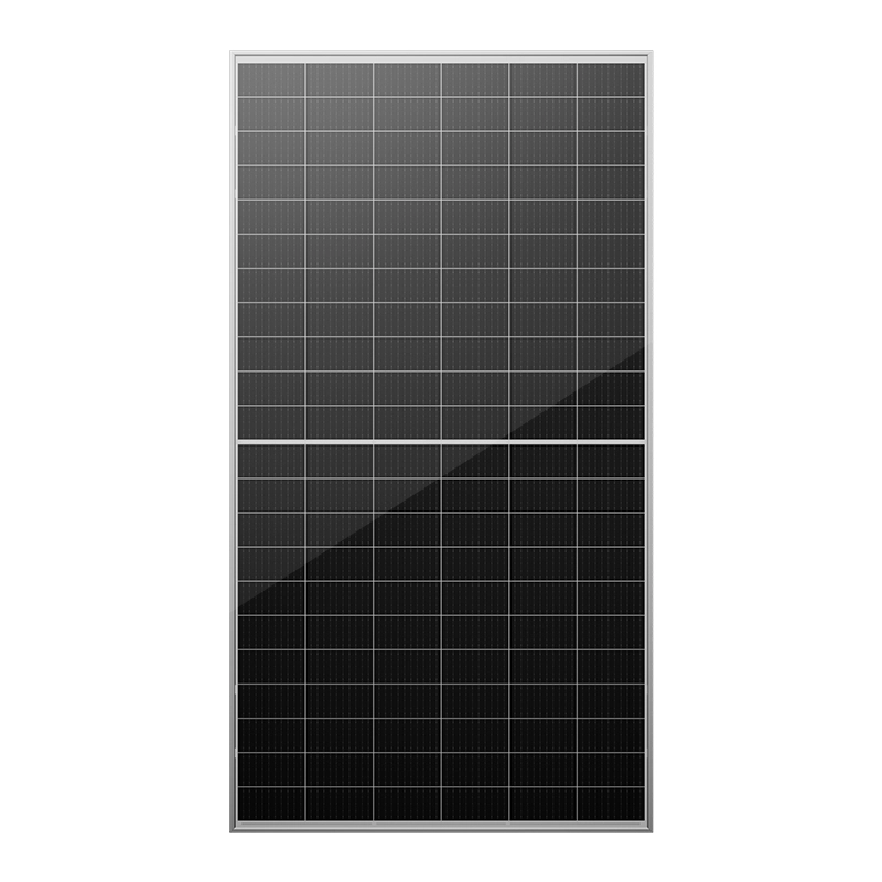
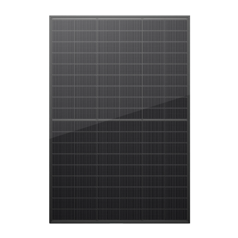
For commercial and industrial projects, N-type TOPCon modules are the current industry standard, offering higher efficiency, better temperature performance, and longer degradation warranties than older PERC technology.
Key PV Specifications
- Module type: N-type TOPCon bifacial dual-glass modules, 550–580Wp each
- Conversion efficiency: 22%+
- Temperature coefficient: -0.30%/°C
- Product warranty: 15 years; linear power warranty: 30 years (≤1% first-year degradation, ≤0.4% annual degradation thereafter)
- Total modules for 1MW DC: Approximately 1725–1820 units
- DC-to-AC ratio: 1.2:1 to 1.4:1 is recommended for solar-plus-storage systems. Oversizing the PV array relative to the PCS maximizes energy yield and improves utilization of the battery system.
PV arrays can connect to the storage system via either AC coupling (separate solar inverters feeding into the AC bus) or DC coupling (PV and battery share a single PCS, connecting on the DC side). DC-coupled systems are generally 2–3% more efficient overall, as they avoid an extra DC-AC-DC conversion step when charging the battery directly from solar.
2.2 Battery Energy Storage System
Batteries represent 50–60% of total system cost and are the most technology-critical component. Today, lithium iron phosphate (LFP) chemistry is the undisputed standard for commercial stationary storage, offering excellent cycle life, thermal stability, and cost performance.
Cell & System Architecture
A typical 2MWh system uses a three-level hierarchy: cells → modules → battery clusters → full system.
- Cell level: 280–314Ah prismatic LFP cells, 3.2V nominal, 6000+ cycle life at 0.5C, 25°C, 80% end-of-life capacity.
- Module level: Series-connected cells forming a ~330V, 280Ah module (~93kWh each).
- Cluster level: 4 modules in series form a single battery cluster at ~1330V nominal, ~373kWh per cluster.
- System level: 5–8 parallel clusters or modular units deliver a total nominal capacity of approximately 2MWh, with 10–15% top-end capacity margin for real-world operating conditions.
High-voltage systems (1000V+) are now the industry trend for C&I storage, reducing line losses, lowering cabling costs, and minimizing circulating current between parallel clusters.
Battery Management System (BMS)
The BMS acts as the nervous system of the battery bank, using a three-tier architecture:
1. Cell monitoring units (BMU): Measure individual cell voltage and temperature with high accuracy, and perform cell balancing.
2. Cluster control units (BCU): Manage total cluster voltage and current, calculate cluster-level state of charge (SOC) and state of health (SOH), and execute cluster-level protection.
3. System-level BMS host: Coordinates all clusters, communicates with the PCS and EMS, and handles fault diagnosis, alarm logging, and historical data storage.
2.3 Power Conversion System (PCS)
The PCS is the bidirectional bridge between the DC battery bank and the AC electrical system. It controls charging and discharging, manages power quality, and determines whether the system can operate off-grid.
Core PCS Specifications for 1MW Systems
| Parámetro | Typical Value |
| Potencia nominal | 1000 kW (single unit or 8×125kW parallel) |
| AC side voltage | 400V / 690V, 3-phase |
| DC voltage range | 1164 – 1498 V (matched to battery cluster voltage) |
| Peak conversion efficiency | ≥98.5% |
| European efficiency | ≥97.8% |
| Power factor range | 0.9 leading to 0.9 lagging, adjustable |
| Total harmonic distortion (THDi) | ≤3% |
| Capacidad de sobrecarga | 110% continuous; 150% for 60 seconds |
PCS units are classified by operating mode:
- Grid-tied only PCS: Operates in current-source mode, follows grid voltage and frequency, includes anti-islanding protection, and cannot power loads independently.
- Off-grid only PCS: Operates in voltage-source mode, creates its own stable AC voltage and frequency (V/f control), and supports parallel operation with diesel generators.
- Hybrid PCS: Supports both current-source (grid-tied) and voltage-source (off-grid) modes, with fast automatic switching between the two.
2.4 Energy Management System (EMS)
The EMS is the brain of the entire system. It collects real-time data, runs optimization algorithms, and dispatches charging and discharging to maximize value. The quality of EMS logic can change a project’s annual financial return by 15% or more, even with identical hardware.
Core EMS Functions
1. Monitoring and SCADA: Real-time visualization of PV output, battery status, load levels, and grid parameters, with remote access and historical reporting.
2. Safety protection and alarming: Multi-level fault grading, automatic fault location, and notification via email/SMS.
3. Optimized dispatch strategy: The highest-value function, available at three tiers:
- Basic: Fixed time-of-use schedule: Charges and discharges on a fixed schedule based on published utility rate periods. Simple and reliable, but does not adapt to changing conditions.
- Standard: TOU arbitrage + demand charge management: Adds real-time peak shaving to keep maximum demand below a set threshold, delivering both energy cost savings and demand charge reductions.
- Advanced: AI-powered dynamic optimization: Uses machine learning to forecast solar generation, load, and electricity prices, updating the charge/discharge plan every 15–30 minutes to maximize lifetime value. For European markets, advanced EMS systems can also integrate with wholesale day-ahead and intraday markets for additional revenue.
2.5 Auxiliary Support Systems
Gestión térmica
Battery performance, safety, and cycle life all depend on maintaining a consistent operating temperature of 25°C ±10°C.
- Air cooling: Lower cost, simpler maintenance, best for mild climates. Results in larger cell-to-cell temperature differences (5°C+).
- Liquid cooling: More precise temperature control (cell-to-cell delta ≤2°C), higher energy density, and 15–20% longer battery cycle life. Now the preferred and most widely recommended technology for most 1MW+ commercial systems, especially in warm climates.
Fire Safety System
Modern battery storage systems use a multi-layer safety approach:
1. Cell-level thermal stability and flame-retardant materials
2. Module-level thermal barriers to slow heat propagation
3. Cabinet-level automatic fire suppression (clean agent systems such as Novec 1230)
4. Container/building-level fire detection, ventilation, and external fire protection
5. Full integration with BMS and PCS for automatic shutdown on thermal event detection
Electrical Protection & Grounding
- Grid connection cabinet with main breaker, disconnect switch, surge protection, and revenue metering
- Multi-stage lightning and surge protection on both DC and AC sides
- Unified grounding grid with ≤4Ω earth resistance
- Optional power quality equipment (APF, SVG) for harmonic and reactive power compensation
2.6 Modular Standard Product Solutions for 1MW/2MWh Deployments
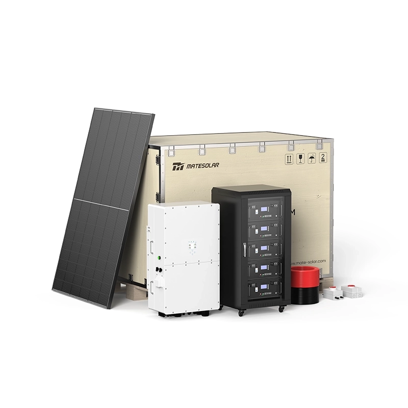
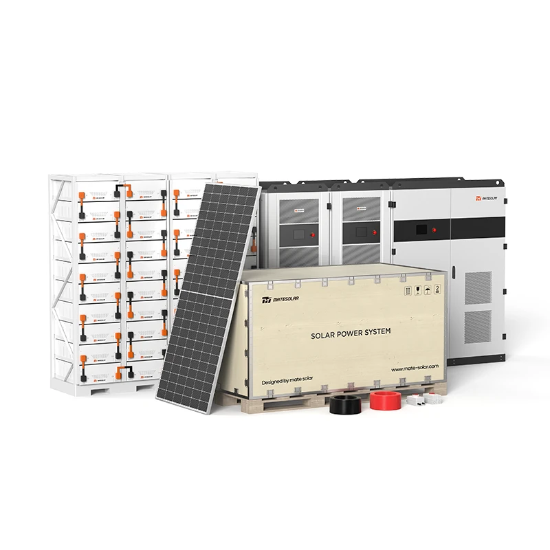
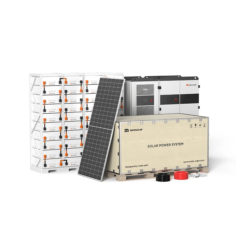
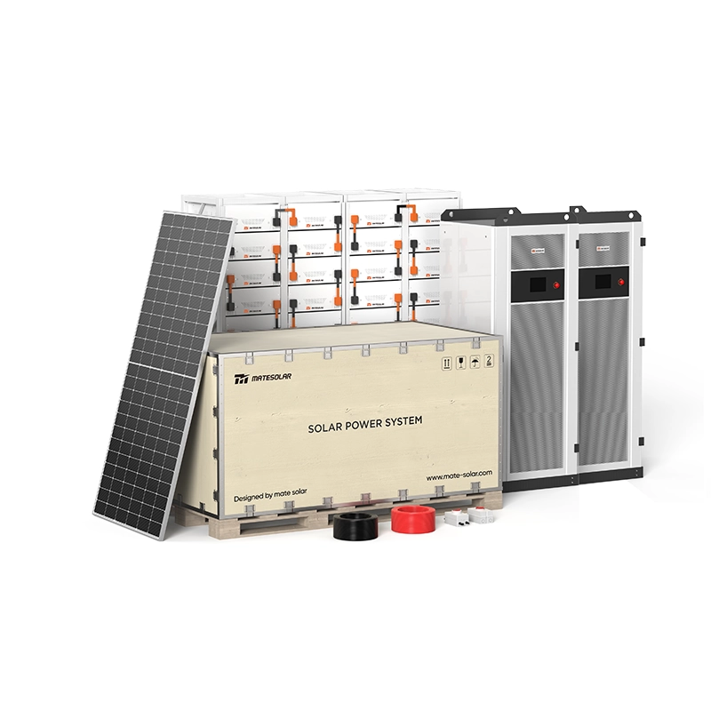
Most modern 1MW/2MWh commercial storage systems are built from standardized, factory-preassembled units that are paralleled on site to reach the target capacity. This modular approach cuts installation time, reduces on-site labor costs, and ensures consistent factory-tested quality. Our product portfolio includes two purpose-built solutions tailored to this power range, serving North America, Europe, and Latin American markets.
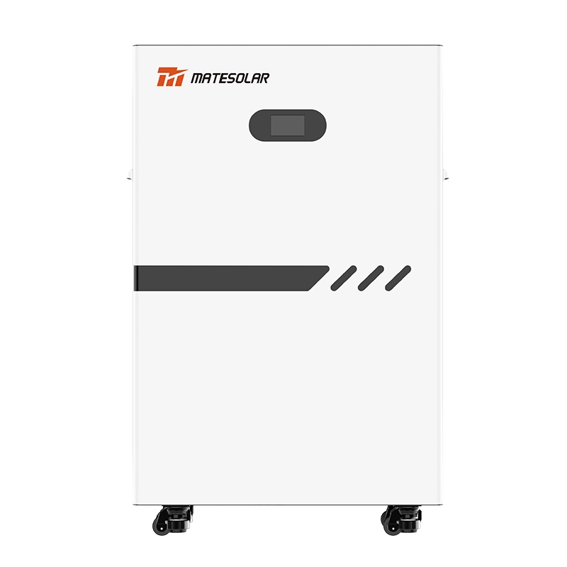
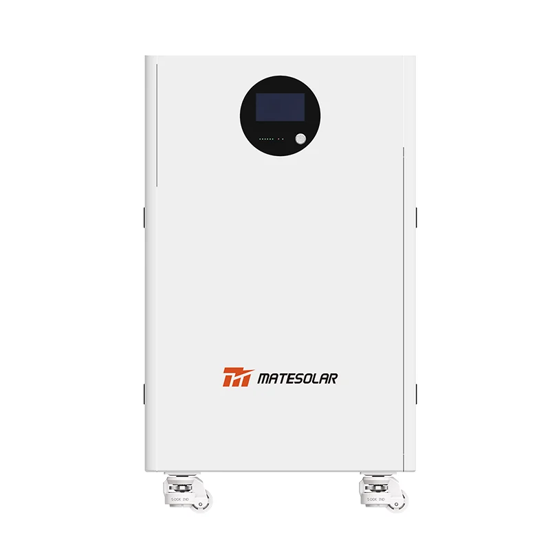
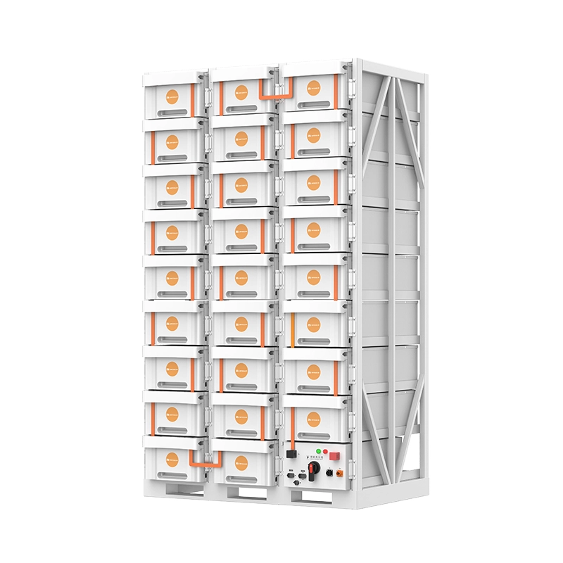
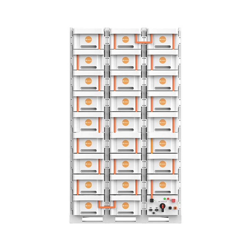
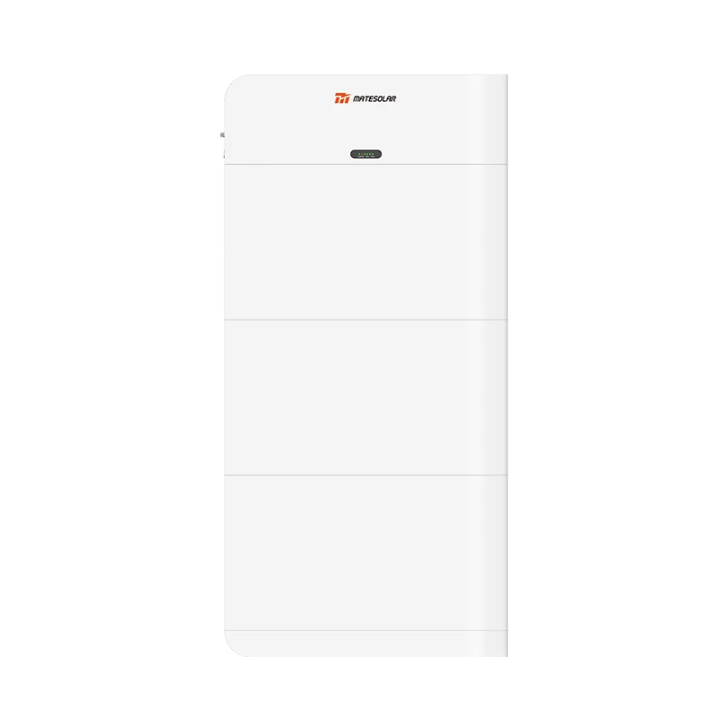
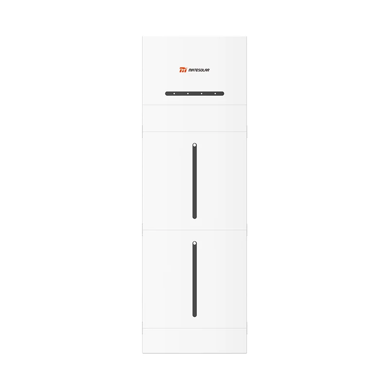
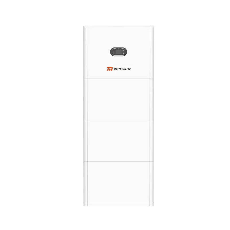
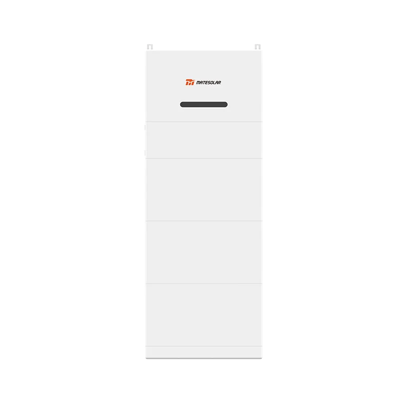
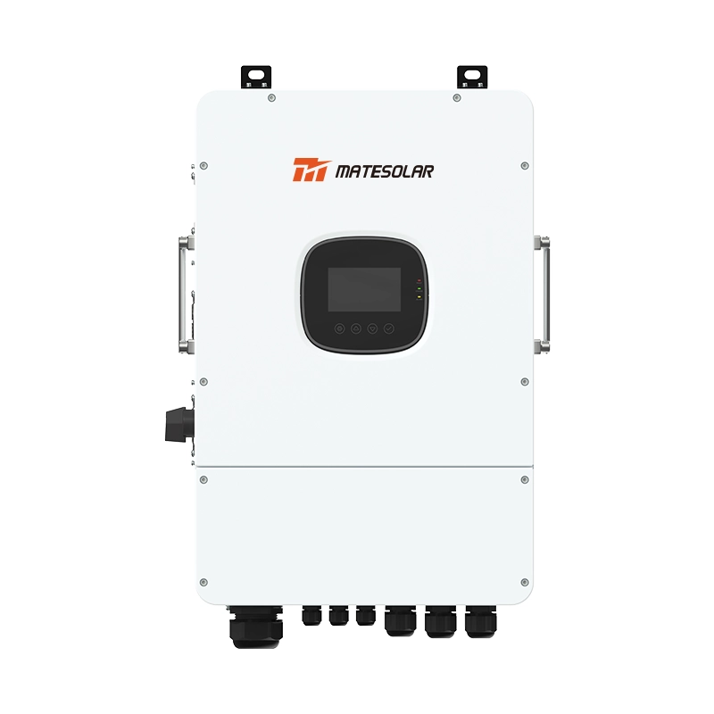
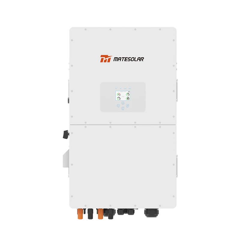
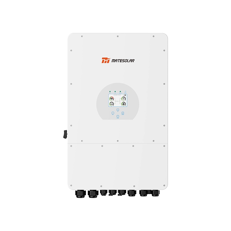
2.6.1 125kW / 261kWh Liquid-Cooled Outdoor Cabinet (Flagship Best-Seller)
Our highest-volume liquid-cooled outdoor storage cabinet is the industry’s most popular building block for 1MW/2MWh C&I projects. Eight units paralleled together deliver exactly 1MW of power output and 2.088 MWh of usable battery capacity, perfectly matching the standard 1MW/2MWh system specification with minimal oversizing waste.
Standard global model specifications:
- Rated power: 125 kW bidirectional
- Nominal energy capacity: 261 kWh
- Thermal management: Active liquid cooling with precise temperature control (≤2°C cell-to-cell temperature difference)
- Protection rating: IP55 for direct outdoor installation
- Cycle life: 6000+ cycles at 0.5C, 80% end-of-life capacity
- Compliance: IEC 62619, CE certified for European and global markets
For the North American market, we offer a 135kW / 261kWh UL-certified variant built to UL 9540 and UL 1973 standards, fully compliant with local utility interconnection rules and National Fire Code requirements. The standard 125kW/261kWh configuration is featured in our product catalog, with full technical datasheets, dimensional drawings, and performance data available on the dedicated product page.
This liquid-cooled design is our primary recommended configuration for all new projects. It delivers superior battery life, higher energy density, and better high-temperature performance compared to air-cooled alternatives, and is fully compatible with grid-tied, hybrid, and off-grid system architectures.
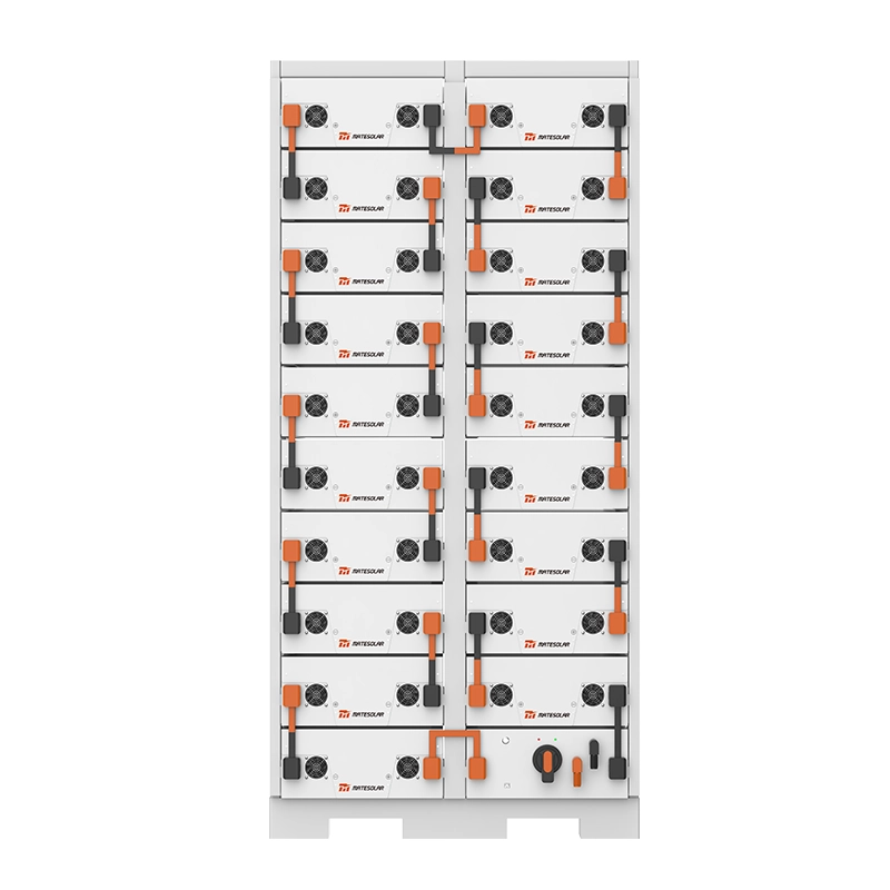
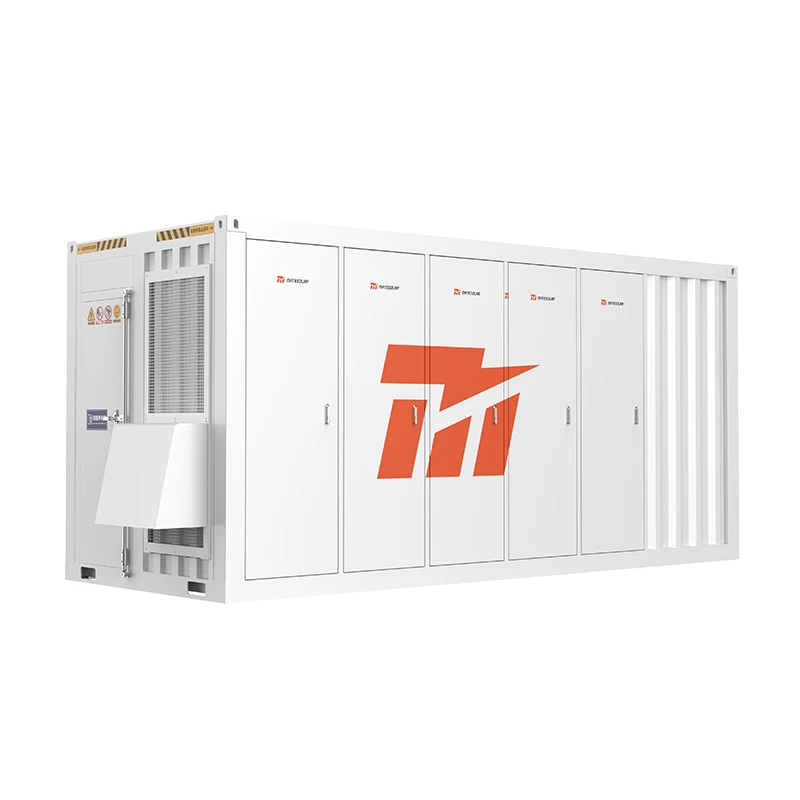
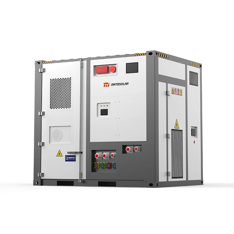
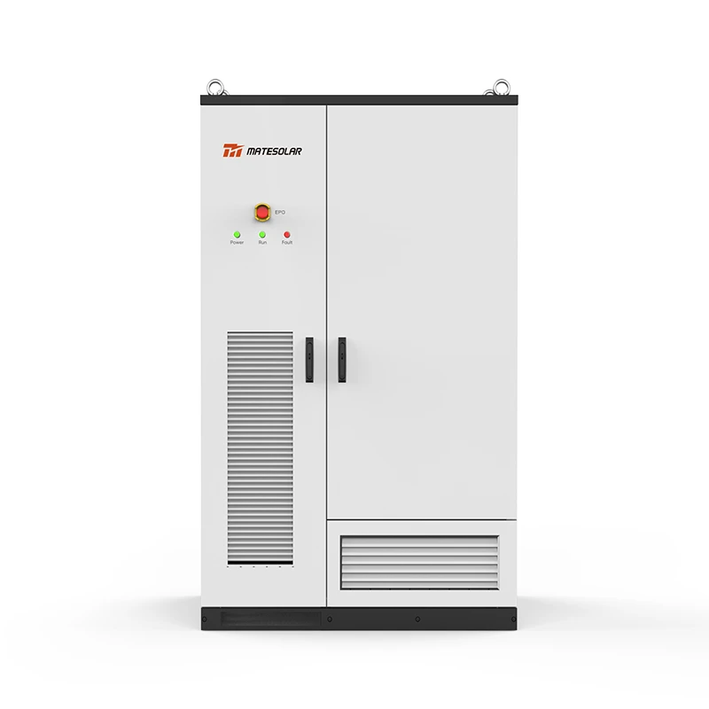
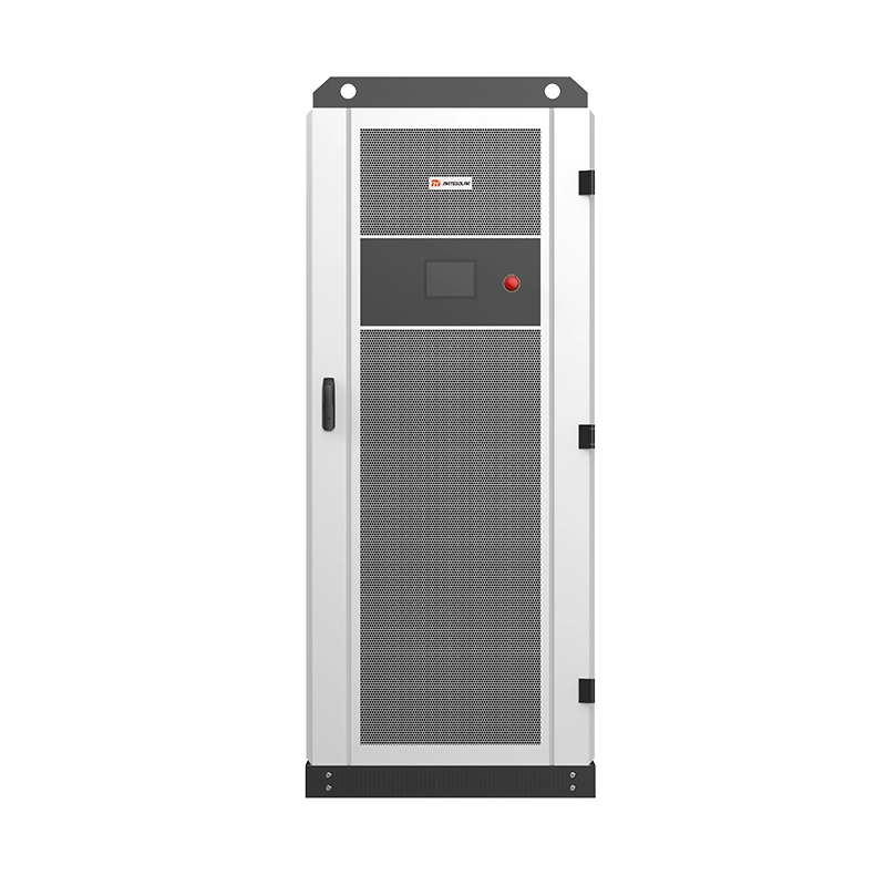
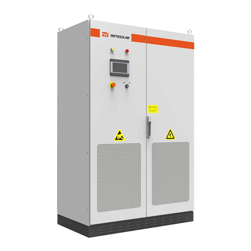
2.6.2 40ft Air-Cooled Containerized Storage System
For budget-sensitive projects or installations in consistently mild climate zones, we also offer a 40-foot air-cooled containerized energy storage system as a cost-competitive alternative. The fully integrated unit houses all battery racks, PCS, fire suppression, and control systems inside a standard 40ft shipping container, enabling single-unit delivery and fast plug-and-play deployment.
While liquid cooling is now the industry’s primary recommended technology for C&I storage due to its proven longevity and thermal performance, our air-cooled container remains a viable, well-proven option for projects with tighter capital budgets or operating environments with moderate year-round temperatures. It can be configured to match 1MW/2MWh system requirements and supports all three operating modes.
3. Grid-Tied Solar Storage Systems: Deep Dive
3.1 How It Works
A grid-tied (or utility-interactive) solar-plus-storage system operates in parallel with the public grid at all times. It uses the grid as its voltage and frequency reference, and cannot function independently.
In normal operation, on-site solar power feeds the facility load first. Any surplus solar can charge the battery or be exported to the grid. The battery can also charge from the grid during low-price off-peak hours, then discharge during high-price peak hours to reduce the facility’s utility bill.
By code, all grid-tied systems include mandatory anti-islanding protection. If the grid loses power, the system must shut down within 2 seconds to avoid energizing downed lines and endangering utility workers. This means a grid-tied system cannot provide backup power during outages.
3.2 System Architecture
Grid-tied systems use either AC-coupled or DC-coupled topology. AC coupling is ideal for retrofitting storage onto an existing solar system, while DC coupling is more efficient and cost-effective for new build projects.
Key equipment characteristics:
- PCS: Grid-tied only, current-source mode; lower cost than hybrid equivalents
- Battery: Selected first and foremost for long cycle life (6000+ cycles), since daily full charge-discharge cycles are the norm
- EMS: Focused exclusively on economic optimization — time-of-use arbitrage, demand charge management, and export control
Our 125kW liquid-cooled cabinet units are particularly well-suited for grid-tied arbitrage and demand charge management projects, thanks to their long cycle life, high round-trip efficiency, and modular scalability.
3.3 Ideal Use Cases & Customer Profiles
Grid-tied storage is the best choice when financial return is the primary goal and grid reliability is acceptable.
Best-fit scenarios:
1. Urban and suburban commercial/industrial facilities with reliable grid service (<10 hours of outages per year)
2. Regions with large time-of-use price differences or high demand charges, including most of North America, Western Europe, and larger Latin American economies
3. Facilities under two-part tariff structures (energy charge + demand charge)
4. Existing solar systems with low self-consumption rates, where adding storage shifts midday solar to higher-value evening hours
Typical customers:
- Medium to large manufacturing facilities with 2000kVA+ transformers
- Distribution centers, cold storage facilities, and large commercial buildings
- Financial decision-makers focused on measurable ROI and predictable payback
- Facilities in well-developed industrial parks with stable grid infrastructure
3.4 Operating Strategy & Financial Performance
Typical Daily Operating Profile
For a facility with a standard 4-tier time-of-use rate (off-peak, mid-peak, on-peak, critical peak):
- 00:00 – 07:00 (off-peak): Battery charges from the grid up to ~90% SOC
- 07:00 – 09:00 (mid-peak): Battery stands by; solar ramps up and feeds on-site load
- 09:00 – 11:00 (on-peak): Battery discharges to reduce grid import
- 11:00 – 13:00 (mid-peak): Battery stands by; excess midday solar recharges the battery
- 13:00 – 17:00 (on-peak): Second discharge cycle
- 17:00 – 21:00 (critical peak): Third discharge if remaining capacity allows
- 21:00 – 23:00 (mid-peak): Battery stands by
- 23:00 – 24:00 (off-peak): Grid charging begins again
In European markets with dynamic wholesale pricing, advanced EMS systems can adjust this schedule daily to capture the largest price spreads, rather than following fixed time-of-use bands.
Financial Estimate (1MW/2MWh Grid-Tied System)
| Cost Item | Typical Range (USD) |
| 1MW PV array (installed) | $45,000 – $55,000 |
| 2MWh battery storage system (8× 261kWh liquid-cooled cabinets) | $220,000 – $260,000 |
| Grid interconnection, switchgear & installation | $20,000 – $30,000 |
| EMS, monitoring & commissioning | $5,000 – $15,000 |
| Total installed cost | $290,000 – $360,000 |
| Annual Revenue & Savings | Typical Estimate |
| Time-of-use arbitrage savings | $38,000 – $52,000 |
| Reducción de la tarifa a la demanda | $22,000 – $32,000 |
| Increased solar self-consumption value | $10,000 – $18,000 |
| Demand response / ancillary service revenue | $3,000 – $15,000 |
| Valor anual total | $73,000 – $117,000 |
Note: European projects may see higher ancillary service revenue from frequency containment reserve (FCR) and balancing markets, offsetting tighter pricing competition in the region.
With annual O&M costs of approximately 1.5% of initial investment, a well-sited grid-tied 1MW/2MWh system typically delivers a simple payback period of 3.5 to 5.5 years, with an internal rate of return (IRR) of 18–28% over the 15-year project life.
3.5 Advantages & Limitations
| Ventajas | Limitations |
| Lowest upfront cost of the three architectures | Provides no backup power during grid outages |
| Most mature, standardized technology | Financial performance is highly sensitive to utility rate structures |
| Predictable returns and well-understood operating model | Subject to utility interconnection rules and approval processes |
| Simplest operation and lowest maintenance burden | Cannot operate independently from the grid |
4. Off-Grid Solar Storage Systems: Deep Dive
4.1 How It Works
An off-grid (or standalone) solar-plus-storage system has no connection to the public utility grid. It generates and manages all of its own power, forming an independent microgrid.
During daylight hours, the PV array powers the site load and charges the battery bank. At night or during extended cloudy weather, the battery discharges to supply the load. A backup diesel (or gas) generator is almost always included to cover extended periods of low solar input and to provide equalization charging for the batteries.
The entire design revolves around energy balance: ensuring that even in the worst weather month, the system can reliably power critical loads.
4.2 System Architecture
Off-grid systems typically use a DC-bus architecture. Solar charges the battery bank through MPPT charge controllers, and an off-grid inverter draws from the battery to supply AC loads. The backup generator connects either on the AC side in parallel with the inverter, or via a rectifier on the DC side.
Key equipment characteristics:
- Inverter/PCS: Must have full V/f voltage-source control capability to establish and maintain stable AC output. Dynamic response and overload capability are critical for starting motors and other inductive loads.
- Battery bank: Sized with significant spare capacity. Depth of discharge is typically limited to 60–70% to reserve capacity for consecutive cloudy days.
- PV array: Oversized relative to grid-tied systems — often 1.5–2x the battery power rating — to ensure fast charging and reliable energy input.
- Backup generator: Sized to match peak site load, and included as standard for reliability.
For remote off-grid sites across Latin America, Africa, and rural regions, our 40ft air-cooled container offers a robust, all-in-one deployment that can be paired with diesel gensets and PV arrays for standalone microgrid operation.
4.3 Ideal Use Cases & Customer Profiles
Off-grid systems are the only viable solution where grid power is unavailable or fundamentally unreliable.
Best-fit scenarios:
1. Remote mines, drilling sites, and construction camps with no grid access
2. Island resorts, eco-lodges, and remote coastal facilities
3. Rural industrial sites and agricultural operations far from the utility grid
4. Areas with extremely poor grid reliability (frequent multi-day outages, voltage collapse, frequency instability)
5. Sites where building a grid extension would cost more than the off-grid system itself
Typical customers:
- Mining operators and oil & gas field operators
- Remote resort and tourism developers
- Infrastructure and construction project managers
- Operations currently running 100% on diesel generators, facing very high fuel and transport costs
- Decision-makers who prioritize reliable power first, and cost savings second
4.4 Capacity Sizing Methodology
Sizing an off-grid system is far more nuanced than sizing a grid-tied one. The process follows four core steps:
1. Load audit: Catalog all loads, their power draw, and daily run time. Separate critical loads from non-essential loads for priority shedding.
2. Define autonomy requirement: Specify how many consecutive cloudy days the system must survive without generator support. Typical standards are 3–5 days for general use, 5–7 days for critical facilities.
3. Calculate required PV capacity: Based on the lowest-solar month of the year, with a safety margin of 1.3–1.8x depending on reliability requirements.
4. Calculate required battery capacity:
For a 1MW/2MWh off-grid system, the configuration is best suited for sites with high peak power demand but moderate daily energy consumption — for example, mining operations with heavy intermittent loads. For 24-hour continuous base loads, 2MWh of storage only supports roughly 2 hours of full 1MW load, so additional battery capacity or generator runtime is required.
4.5 Financial Performance
Off-grid economics are not driven by arbitrage — they are driven by diesel fuel displacement. In remote locations, delivered diesel cost can be extremely high once transport, generator maintenance, and labor are included.
Financial Estimate (1MW PV + 2MWh Storage + 500kW Diesel Generator)
| Cost Item | Typical Range (USD) |
| 1MW PV array (ground-mount) | $50,000 – $65,000 |
| 2MWh battery storage system (containerized) | $230,000 – $280,000 |
| 500kW diesel generator set | $35,000 – $50,000 |
| Off-grid controls, switchgear & installation | $25,000 – $35,000 |
| Total installed cost | $340,000 – $430,000 |
With a typical diesel generation cost of $0.30–$0.55 per kWh in remote locations, replacing diesel with solar-plus-storage at a levelized cost of roughly $0.08–$0.12 per kWh delivers dramatic savings. For a site displacing 700,000–900,000 kWh of diesel generation per year, simple payback typically falls between 2.0 and 3.5 years — often faster than grid-tied systems.
4.6 Advantages & Limitations
| Ventajas | Limitations |
| Complete energy independence, no reliance on utility grid | Highest upfront capital cost |
| Exceptional economics when replacing expensive diesel | More complex design; poor sizing leads to either unreliability or over-investment |
| No utility interconnection process or approval required | Higher maintenance burden, including generator servicing |
| Containerized systems are mobile and relocatable | Backup generator still produces noise and emissions |
5. Hybrid (Grid-Tied + Off-Grid) Solar Storage Systems: Deep Dive
5.1 How It Works
A hybrid (or grid-interactive) solar-plus-storage system combines the best of both grid-tied and off-grid designs. Under normal conditions, it operates exactly like a grid-tied system, optimizing for cost savings, demand charge reduction, and solar self-consumption. When the grid fails, it automatically disconnects from the grid and switches to off-grid mode, powering designated critical loads independently.
Premium hybrid systems achieve this transition in 20 milliseconds or less, so sensitive electronic loads never see an interruption. Lower-cost systems may have switchover times of 100ms to 1 second, which is acceptable for lighting and motor loads but not for precision equipment.
In short: a hybrid system saves you money when the grid is up, and keeps your critical operations running when the grid goes down.
5.2 Core Architecture & Key Technologies
A hybrid system uses a bidirectional hybrid PCS that can operate in both current-source (grid-following) and voltage-source (grid-forming) modes. A fast-acting grid disconnect switch sits between the utility and the system. When the EMS detects a grid fault, it opens the switch and commands the PCS to switch from grid-following to grid-forming mode.
Most installations divide facility loads into two groups:
- Critical loads: Powered in both grid-tied and off-grid mode
- Non-critical loads: Powered only when the grid is available, automatically shed during outages to maximize backup runtime
The four biggest technical challenges in hybrid systems are:
1. Seamless transition: Fast, glitch-free mode changeover without load disruption
2. Accurate islanding detection: Reliably distinguishing true grid outages from temporary voltage sags
3. Off-grid power balance: Fast dynamic response to load changes while maintaining stable voltage and frequency
4. Intelligent load shedding: Progressive, priority-based load reduction as battery SOC drops during extended outages
For hybrid systems requiring fast mode switching, our UL-certified 135kW North American model and CE-certified 125kW European model both support seamless grid-to-island transition in under 20ms, making them ideal for facilities with critical production or IT loads.
5.3 Ideal Use Cases & Customer Profiles
Hybrid systems are the fastest-growing segment of C&I storage, because they address the most common customer reality: the grid is mostly reliable, but outages happen often enough to hurt business.
Best-fit scenarios:
1. Manufacturing facilities where downtime causes product loss, equipment damage, or missed delivery penalties
2. Commercial buildings, data centers, hospitals, and cold storage facilities where power interruptions have direct financial costs
3. Regions with occasional grid outages, load shedding, or voltage sags (10–50 hours of outage per year)
4. Businesses that want demand charge and TOU savings, plus backup resilience, from a single investment
5. Facilities planning future microgrid expansion or virtual power plant participation
Typical customers:
- Food and beverage processors, electronics manufacturers, and other process industries
- Shopping centers, hotels, and healthcare clinics
- Operations with per-inventory outage costs ranging from thousands to hundreds of thousands of dollars
- Decision-makers willing to pay a modest premium for both savings and resilience
5.4 Operating Strategies
Grid-Tied Mode (99%+ of operating time)
Hybrid systems run the same economic optimization strategies as pure grid-tied systems, with one key difference: they always reserve a portion of battery capacity for backup.
A typical reserve setting is 20–30% SOC. This reserved capacity is not used for daily arbitrage, so pure financial return is slightly lower than a comparable grid-tied system. The higher the reserve, the longer the backup runtime, but the lower the daily savings. The optimal reserve level depends on local grid reliability and the cost of an outage.
Off-Grid Mode (during grid outages)
When an outage occurs:
1. Non-critical loads are automatically disconnected
2. The PCS switches to voltage-source mode and establishes the microgrid
3. Solar continues to operate, powering loads first and recharging the battery when possible
4. The battery discharges to cover the difference between load and solar output
5. As battery SOC drops, additional non-critical loads are shed in priority order
6. If equipped, a backup generator starts automatically when SOC reaches a low threshold
7. When grid power returns and stabilizes, the system re-synchronizes and reconnects automatically
Backup Runtime Estimates (1MW/2MWh Hybrid System)
Based on usable backup capacity of 90% → 20% SOC:
| Critical Load Power | Approximate Backup Runtime | Typical Application Example |
| 200 kW | ~7 hours | Office systems, lighting, security, small critical equipment |
| 500 kW | ~2.8 hours | Partial production lines, core process equipment |
| 800 kW | ~1.75 hours | Majority of plant operations |
| 1000 kW | ~1.4 hours | Full facility load |
During daylight hours, solar generation extends backup runtime significantly. In good sun conditions, a 1MW array can fully cover a 200–400kW critical load indefinitely, with the battery only handling peaks and clouds.
5.5 Financial Performance
Hybrid systems cost roughly 15–20% more than equivalent grid-tied systems, due to the more expensive hybrid PCS, transfer switchgear, and more sophisticated EMS software.
However, their total value includes both measurable cost savings and the avoided cost of power outages. For many businesses, the outage avoidance value alone justifies the price premium.
| Cost / Value Item | Grid-Tied System | Hybrid System |
| Total installed cost (1MW/2MWh) | $290k – $360k | $340k – $420k |
| Annual energy & demand savings | $73k – $110k | $62k – $95k (slightly lower due to backup reserve) |
| Annual outage avoidance value | $0 | $25k – $80k+ (depends on outage frequency and cost) |
| Período de recuperación simple | 3.5 – 5.5 years | 3.8 – 6.0 years |
For facilities where even a single 4-hour outage can cost $20,000+ in lost production and spoiled material, the hybrid premium typically pays for itself in 2–3 years through avoided downtime alone — on top of the ongoing utility bill savings.
5.6 Advantages & Limitations
| Ventajas | Limitations |
| Best of both worlds: daily cost savings + outage resilience | 15–20% higher upfront cost than grid-tied |
| Seamless backup power for critical loads | Backup runtime is limited by battery capacity |
| Strong foundation for future microgrid or VPP upgrades | More complex controls require high-quality hardware and software |
| Flexible: backup reserve level can be adjusted seasonally | Reserved backup capacity reduces daily arbitrage earnings |
6. Full Comparison: Grid-Tied vs. Off-Grid vs. Hybrid
The table below summarizes the differences across technical, financial, operational, and application dimensions.
| Comparison Category | Conexión a la red | Hybrid | Sin conexión a la red |
| Technical | |||
| Grid connection | Permanent parallel connection | Automatic connect / disconnect | No grid connection at all |
| Power during grid outage | None — anti-islanding protection shuts system down | Yes — seamless switch to off-grid mode | Always independent power |
| PCS operating mode | Current source only | Current source + voltage source | Voltage source only |
| Capacidad de arranque en negro | No | Yes (premium models) | Yes, required |
| System peak efficiency | Highest | Medio | Baja |
| Financial | |||
| Upfront capital cost | Lowest | Medium-high | Highest (includes generator) |
| Primary revenue driver | TOU arbitrage + demand reduction | Savings + outage cost avoidance | Diesel fuel replacement |
| Typical simple payback | 3.5 – 5.5 years | 3.8 – 6.0 years | 2.0 – 3.5 years (high diesel cost regions) |
| Sensitivity to policy/rates | Very high | Moderado | Bajo |
| Operacional | |||
| Daily maintenance burden | Very low | Bajo | High (includes generator servicing) |
| Battery cycling frequency | 1–2 full cycles per day | ~1 cycle per day + standby | Daily cycling, often deeper |
| Spare parts availability | Excelente | Bien | More specialized |
| Producto recomendado | 125kW liquid-cooled cabinet | 125kW / 135kW liquid-cooled cabinet | 40ft air-cooled container (budget) / liquid-cooled cabinets (premium) |
| Application Fit | |||
| Excellent grid reliability | ✅ Best choice | Overkill | No aplicable |
| Occasional short outages | Acceptable risk | ✅ Best choice | Over-sized |
| No grid or frequent long outages | Not viable | Not viable | ✅ Best choice |
| Primary goal: maximum ROI | ✅ Best choice | Good, but slightly lower | Different economic model |
| Primary goal: 100% uptime | Not suitable | Very good | Best for no-grid areas |
7. How to Select the Right System for Your Operation
Choosing between the three architectures follows a clear decision framework:
Step 1: Evaluate your grid service quality
- No grid access at all: Off-grid is the only option.
- Frequent or long-duration outages (>50 hours/year): Evaluate hybrid + backup generator, or full off-grid depending on outage length.
- Occasional short outages (5–50 hours/year): Hybrid is usually the best balance of cost and resilience.
- Extremely reliable grid (<5 hours/year outage): Grid-tied delivers the best pure financial return.
Step 2: Quantify the cost of downtime
Estimate the direct and indirect cost of a single 4-hour outage: lost production, spoiled material, equipment restart costs, missed deadlines, and safety risks.
- If annual expected outage losses exceed $30,000, a hybrid system almost always justifies its premium.
- If outage costs are negligible, grid-tied is the most economical choice.
Step 3: Model the financial return
Calculate projected savings from time-of-use arbitrage, demand charge reduction, and solar self-consumption improvement. Compare against total installed cost to estimate payback and IRR. For European projects, be sure to include potential ancillary service and wholesale market revenue streams.
Step 4: Consider future plans
If you expect to expand your facility, add EV charging, participate in demand response programs, or build out a site microgrid, a hybrid architecture with modular liquid-cooled cabinets offers much greater long-term flexibility than a basic grid-tied or single-container system.
8. Critical Engineering Best Practices
8.1 Optimizing the PV-to-Storage Ratio
The 1MW / 2MWh ratio is a strong baseline, but every project should be tuned to local conditions:
- High-solar regions with midday oversupply: lean toward more storage per MW of PV
- Grid arbitrage is the main goal: 0.5C (2MWh per 1MW) is usually optimal
- Off-grid systems: use higher PV-to-storage ratios (1.5–3x) for faster charging and cloudy-day resilience
8.2 Balancing Battery Life Against Financial Return
Battery cycle life has a direct impact on 10–15 year project returns. Key operating best practices:
- Limit regular discharge depth to 70–80% for daily cycling applications
- Avoid prolonged operation at 100% or 0% SOC
- Maintain proper operating temperature with active thermal management. Liquid cooling systems consistently deliver 15–20% longer service life than air-cooled equivalents in warm climates.
- Use EMS algorithms that explicitly account for battery degradation cost when optimizing dispatch decisions
8.3 Grid Interconnection Compliance
All grid-tied and hybrid projects must follow local utility rules and national electrical codes. Key requirements typically include:
- Certified anti-islanding protection per local standards (IEEE 1547 in North America, VDE-AR-N 4105 in Germany, etc.)
- Compliance with grid code requirements for voltage and frequency ride-through
- Approved metering arrangements for import, export, and net metering
- Formal utility interconnection application and approval process
8.4 Fire Safety & Risk Mitigation
Safety is non-negotiable for battery storage installations. Always:
- Select battery products certified to UL 9540, IEC 62619, and applicable local standards
- Follow required setbacks and fire separation distances
- Install multi-sensor fire detection (gas, temperature, smoke) with automatic suppression
- Integrate fire safety controls with BMS and PCS for automatic shutdown
- Document clear operating procedures and emergency response plans
9. Industry Standards & Certifications
A high-quality commercial storage system should comply with leading international standards:
- Seguridad IEC 62619, UL 1973, UL 9540, UL 9540A (thermal runaway testing)
- PCS / inverter: IEC 61683, IEEE 1547, UL 1741, EN 50549
- System-level: IEC 62933 series, NFPA 855, NEC Article 706
- Quality management: ISO 9001, ISO 14001, ISO 45001
For projects in North America, UL certification is generally required for utility interconnection and code compliance. For European markets, CE compliance aligned with relevant EN standards is mandatory. For Latin America, IEC-compliant systems with local national certifications are standard. Our flagship 125kW liquid-cooled cabinet holds all key global certifications to support cross-region project deployment.
10. Frequently Asked Questions (FAQ)
Q: How much does a 1MW/2MWh commercial solar storage system cost?
A: A fully installed 1MW/2MWh system ranges from approximately $290,000 to $430,000 USD, depending on system type (grid-tied, hybrid, or off-grid), site conditions, and component specifications. Grid-tied systems with modular liquid-cooled cabinets are the least expensive; off-grid systems with backup generators are the most expensive.
Q: What standard storage units do you offer to build a 1MW/2MWh system?
A: Our flagship solution is the 125kW/261kWh liquid-cooled outdoor cabinet; eight units paralleled create a perfectly sized 1MW/2.088MWh system. For North American projects, we offer a 135kW/261kWh UL-certified variant. We also provide a 40ft air-cooled containerized option for budget-focused projects. Full details for our standard liquid-cooled model are available on our product page, and custom configurations are available upon request.
Q: What is the typical payback period?
A: For grid-tied systems in regions with good time-of-use spreads and high demand charges, simple payback is typically 3.5 to 5.5 years. For off-grid systems replacing expensive diesel, payback can be as short as 2 to 3.5 years. Hybrid systems fall in between, with slightly longer payback but added resilience value.
Q: How long do the batteries last?
A: High-quality LFP battery systems are warrantied for 10–15 years or 6000+ full cycles, and typically remain above 80% of original capacity at end of warranty. With proper liquid cooling and conservative operating strategies, many systems last 15–20 years in commercial service.
Q: Do I need utility approval to install a grid-tied or hybrid system?
A: Yes, almost all utility territories require formal interconnection approval for systems over a certain size. The process includes submitting system design documents, meeting grid code requirements, and installing approved metering. An experienced EPC or system integrator typically handles this process.
Q: Can a hybrid system power my entire facility during an outage?
A: It can, but sizing the system to power every load during a long outage is usually not cost-effective. Most hybrid projects are designed to power designated critical loads only — typically 20–60% of total facility load — to maximize backup runtime at reasonable cost.
Q: How much roof or ground space do I need?
A: For the 1MW solar array, plan for approximately 8,000–14,000 m² depending on mounting type. A 2MWh battery system built with our modular liquid-cooled cabinets only requires 25–35 m² of paved, level ground with access for installation and maintenance.
Q: Can the system be expanded later?
A: Yes. Modular cabinet-based systems like our 125kW liquid-cooled unit are designed for easy scalability. Most EMS platforms support adding extra battery clusters or PV capacity as your load or energy goals grow.
For commercial and industrial facilities across North America, Europe, Central America, and Latin America, solar-plus-storage is no longer just a sustainability statement — it is a core operational and financial investment that reduces energy costs, protects against volatile electricity prices, and improves power resilience.
The 1MW/2MWh configuration offers an unmatched balance of standardization, cost efficiency, and versatility. Whether your priority is maximum financial return, uninterrupted operations, or complete energy independence, there is a system architecture and product configuration aligned with your goals.
If you are evaluating a solar storage project for your facility or client site, our team can provide a free, site-specific feasibility assessment including detailed sizing, financial modeling, and system configuration recommendations. Reach out today to request your customized project proposal.