

















Executive Summary: The Trillion-Dollar Transition
The energy storage industry has crossed a historic threshold in 2026. No longer a policy-driven appendage to renewable energy projects, storage has evolved into a market-driven, trillion-dollar ecosystem that forms the structural backbone of modern power systems worldwide. Global cumulative installed energy storage capacity reached 277.7 GW / 679.6 GWh by the end of 2025, with annual additions of 112.5 GW / 310.6 GWh representing year-over-year growth of 51.6% and 77.5%, respectively. The trajectory for 2026 is even more aggressive: analysts project 265 GWh of new installations globally, a 63% increase over 2025.
What distinguishes this moment from previous growth cycles is a fundamental shift in the industry's operating logic. The market has transitioned from policy-mandated deployment to market-driven profitability. Document No. 136 eliminated compulsory storage allocation requirements for new renewable energy projects, forcing the industry to stand on its own economic merits. Simultaneously, Document No. 114 established a national capacity remuneration mechanism, creating a sustainable revenue stream for storage assets. The inclusion of "computing-power-electricity synergy" in government work reports for the first time signals that the explosive growth of AI and data center demand will be a structural driver of storage deployment for years to come.
For professionals working in energy storage—whether developers, engineers, financiers, or system operators—understanding the technical nuances, market dynamics, and operational realities of lithium battery energy storage systems (BESS) is no longer optional. It is the price of admission to a sector that the National Energy Administration projects will attract over RMB 2 trillion in investment during the "15th Five-Year Plan" period alone.
This compendium distills the 18 most critical knowledge domains in lithium battery energy storage, drawing on the latest 2026 standards, market data, and technical specifications. Master ten of these, and you are a true industry insider. Master all eighteen, and you are equipped to lead in the most dynamic energy sector of the decade.
Part I: Market Context — The 2026 Landscape
Before diving into technical specifications, it is essential to understand the market forces shaping the industry in mid-2026.
The North American Opportunity
The United States remains the most significant market for commercial and industrial (C&I) energy storage outside of China. The U.S. installed a record 57 GWh of new battery storage capacity in 2025, a 29% increase over the previous year. The industry is projected to add another 70 GWh in 2026, with nearly 500 GWh expected on the grid by 2030. The North American BESS market was valued at USD 20.82 billion in 2025 and is projected to reach USD 49.34 billion by 2031, representing a compound annual growth rate of 15.48%.
The policy environment remains highly favorable. The Investment Tax Credit (ITC) for standalone energy storage, combined with the Section 45X Advanced Manufacturing Production Credit and domestic content adders, provides powerful financial incentives. California's NEM 3.0 policy, which slashed export rates for rooftop solar by approximately 75% (paying just 2–3 cents per kWh for surplus energy), has created a compelling economic case for storage co-location. Texas, driven by ERCOT market dynamics and AI data center demand, has overtaken California as the largest regional storage market in the U.S.
From Volume to Value
The industry's competitive dynamics have shifted decisively. After brutal price wars that drove system prices from RMB 1.2/Wh to below RMB 0.6/Wh between 2023 and 2025, the 2026 market is defined by competition on total lifecycle value rather than upfront cost. Head players are differentiating through:
- Large-format cell technology (314Ah and beyond)
- Advanced thermal management (liquid cooling becoming standard)
- Intelligent operations and maintenance (AI-driven predictive analytics)
- Superior safety certifications (UL9540A Sixth Edition compliance)
Market concentration has intensified, with the top five battery manufacturers now commanding over 65% of the market. System integrators face similar consolidation pressures, with leading players' order books already filled through the second half of 2026.
Part II: The 18 Essential Knowledge Domains
Knowledge Point 1: The Truth Behind "8,000 Cycle" Ratings
The Question Every Buyer Must Ask
When a manufacturer advertises "8,000 cycles" for their energy storage system, the number is meaningless without understanding the underlying conditions. The standard cycle life claim of 8,000 cycles is predicated on three specific conditions:
| Parameter | Standard Condition | Reality Check |
| Cell Temperature | 25°C (77°F) | Real-world temperature varies significantly |
| Depth of Discharge (DOD) | 100% | Most systems operate at 80–90% DOD |
| State of Health (SOH) | 80% | Some define EOL at 70% |
The Three Interrogations:
1. Temperature Control: Can the manufacturer guarantee cell temperature differentials that keep all cells near 25°C? Liquid cooling systems typically achieve ±2°C uniformity; air-cooled systems may see ±5°C or more. Every 10°C above 25°C can halve battery life.
2. DOD Calculation: If the 8,000-cycle claim is based on 100% DOD, but your system operates at 90% DOD, how does the manufacturer convert the rating? Crucially, are they calculating based on charging energy or discharging energy? Because charge/discharge losses exist, discharge-based calculations provide a more accurate representation of usable energy over the system's lifetime.
3. End-of-Life Definition: Is EOL defined at 80% SOH or 70% SOH? The difference is substantial—a system that reaches 8,000 cycles at 80% SOH might achieve 10,000+ cycles at 70% SOH. Some manufacturers use 70% to make their cycle life claims more attractive; others use 80% as a more conservative and industry-standard benchmark.
Industry Best Practice: Demand that cycle life claims be accompanied by full disclosure of test conditions, including temperature profiles, DOD assumptions, SOH definition, and the specific C-rate used during testing.
Knowledge Point 2: Round-Trip Efficiency (RTE) — The Real Profitability Metric
Round-trip efficiency is the single most important financial metric for any energy storage system. RTE = Discharged Energy ÷ Charged Energy. A system with 90% RTE returns 9 kWh for every 10 kWh charged. The difference between 85% and 92% RTE can represent millions of dollars in lost revenue over a project's lifetime.
The Hidden Losses Most Manufacturers Don't Discuss:
| Loss Category | Typical Range | Often Overlooked? |
| PCS conversion (DC-AC / AC-DC) | 1–3% each way | Nein |
| Battery internal resistance | 2–5% | Nein |
| Auxiliary loads (cooling, BMS, controls) | 3–8% | Ja |
| Cable and interconnection losses | 1–2% | Ja |
| System downtime / faults | Variable | Ja |
Many manufacturers quote RTE based solely on PCS input-to-output measurements, excluding:
- Liquid cooling system power consumption (can be 3–5% of rated power in hot climates)
- Cabinet self-consumption (BMS, monitoring, communications)
- Transformer and cable losses
- Degradation over time
The 2026 Standard: Leading suppliers now offer "system-level RTE guarantees" measured at the point of grid interconnection, inclusive of all parasitic loads. For lithium iron phosphate (LFP) systems, achievable system-level RTE typically ranges from 85% to 92%, depending on operating conditions and C-rate.
Critical Question: Is the manufacturer's RTE claim validated by third-party testing under representative operating conditions, including auxiliary load consumption?
Knowledge Point 3: Fire Safety — The Three-Level Protection Framework
Thermal runaway remains the existential risk for lithium battery energy storage. A robust fire safety system must operate at three distinct levels:
| Ebene | Umfang | Protection Mechanism |
| Level 1: Pack-Level | Individual battery modules | Gas detection, aerosol suppression, cell-level thermal monitoring |
| Level 2: Rack/Cluster-Level | Battery racks within a cabinet | Water mist or gas suppression, isolation contactors |
| Level 3: System-Level | Entire container or enclosure | Room/container flooding, remote monitoring, emergency venting |
The Reality Check: Many manufacturers advertise "three-level protection" but deliver only one or two functional levels. Common tactics include:
- Specifying aerosol suppression at the pack level but omitting rack-level protection
- Combining rack-level and system-level into a single suppression zone
- Providing detection without active suppression at certain levels
The 2026 Standard: GB/T 51048-2025 (effective April 1, 2026) mandates thermal runaway propagation testing reports for large-scale storage projects. Systems that cannot demonstrate effective propagation prevention face significant regulatory and insurance hurdles.
Knowledge Point 4: UL9540A — The Safety Certification That Makes or Breaks Projects
UL9540A is the most rigorous and globally recognized standard for evaluating thermal runaway fire propagation in battery energy storage systems. It is not merely a compliance exercise—it is a bankability requirement for projects in North America and increasingly worldwide.
What UL9540A Tests:
- Whether a thermal runaway event in one cell propagates to adjacent cells
- Whether fire spreads from one module to the next
- Whether an entire rack or container becomes involved
- Whether fire transfers between adjacent containers or structures
The Sixth Edition Revolution: On March 13, 2026, ULSE officially released the sixth edition of UL9540A:2026. The most significant change is the mandatory inclusion of Large-Scale Fire Testing (LSFT) at the installation level. This test involves:
- Deactivating all fire suppression and detection systems
- Igniting a full energy storage unit
- Observing fire propagation to adjacent units
The LSFT requirement means that systems must now demonstrate system-level fire safety, not just cell or module-level performance. Manufacturers must prove that fire will not spread between units—a far more demanding standard than previous editions.
Practical Implication: For commercial and industrial projects in the U.S., a UL9540A report is now a non-negotiable prerequisite for:
- Obtaining building permits
- Securing insurance coverage
- Passing utility interconnection requirements
- Achieving project financing
Without UL9540A certification, your storage equipment may be uninstallable, uninsurable, and unfinanceable.
Knowledge Point 5: Energy Cells vs. Power Cells — One Size Does Not Fit All
The prevailing assumption that "all lithium battery cells are essentially the same" is dangerously wrong. The cell requirements for energy arbitrage (peak shaving, time-of-use shifting) are fundamentally different from those for grid services (frequency regulation, ancillary services).
| Parameter | Energy Cells (0.25–0.5C) | Power Cells (1C–3C) |
| Hauptanwendung | Peak shaving, arbitrage | Frequency regulation, grid support |
| Discharge Duration | 2-4 Stunden | 15 minutes – 1 hour |
| Pulse Capability | Niedrig | Hoch |
| Heat Generation | Mäßig | Hoch |
| Cycle Life at 1C | 8,000+ | 4,000–6,000 |
| Kosten pro kWh | Unter | Höher |
Energy Cell Characteristics:
- Optimized for high energy density and long duration discharge
- Poor pulse performance—cannot respond quickly to frequency deviations
- High internal resistance leads to significant voltage drop under high C-rates
- Rapid degradation when subjected to frequent high-rate cycling
Power Cell Characteristics:
- Optimized for high power density and rapid response
- Can deliver milliseconds-level response for frequency regulation
- Lower energy density; higher cost per kWh
- Better thermal management required due to higher heat generation
The Critical Mistake: Using energy cells in frequency regulation applications leads to rapid capacity fade, thermal management challenges, and poor performance on grid service metrics. Using power cells in energy arbitrage applications destroys the economic case through excessive capital costs.
2026 Trend: The industry is moving toward "dual-use" cells that can perform both functions with acceptable performance, but true optimization still requires application-specific cell selection.
Knowledge Point 6: Balancing Strategies — Passive vs. Active
Within any battery energy storage system, cells inevitably diverge in performance due to manufacturing variations, temperature gradients, and differential aging. Without effective balancing, these divergences compound, reducing usable capacity and creating safety risks.
| Balancing Type | Mechanismus | Vorteile | Benachteiligungen |
| Passive Balancing | Resistive dissipation of excess energy | Simple, low cost | Wastes energy, generates heat, slow |
| Active Balancing (BMU-level) | DC/DC transfer between cells within module | More efficient than passive | Complex, higher cost |
| Active Balancing (Cluster-level) | DC/DC at rack level | Effective across entire cluster | Higher system cost |
| Active Balancing (EMS-driven) | Dispatch-level control of individual clusters | Most flexible, highest efficiency | Requires sophisticated EMS/BMS integration |
Passive Balancing uses resistors to dissipate excess energy from higher-voltage cells until all cells match. This approach is acceptable for small systems (residential, small commercial) but is impractical for large-scale storage due to energy waste and thermal management challenges.
Aktives Auswuchten transfers energy from higher-charge cells to lower-charge cells, preserving the energy. Three main approaches dominate the 2026 market:
1. BMU-integrated DC/DC: Each battery management unit includes DC/DC converters that move energy between cells within a module. Effective but adds cost and complexity.
2. Rack-level DC/DC: A DC/DC converter at the rack level enables balancing across an entire battery cluster. This approach addresses the cluster-level mismatch that BMU-level balancing cannot solve.
3. EMS-driven cluster balancing: The site-level Energy Management System coordinates dispatch across clusters and even individual packs, commanding different charge/discharge currents to achieve balance. This approach requires the highest level of EMS-BMS integration but delivers the best results.
2026 Best Practice: For systems above 1 MWh, active balancing at both the module and cluster levels is increasingly standard. EMS-driven cluster balancing is becoming the differentiator between premium and commodity systems.
Knowledge Point 7: Liquid Cooling — Cold Plate vs. Immersion
As energy density increases and systems scale to multi-MWh capacities, thermal management has become a critical design differentiator. Liquid cooling has largely displaced air cooling in utility-scale and large C&I applications.
| Parameter | Cold Plate (Indirect) | Immersion (Direct) |
| Cooling Medium | Coolant in metal plates | Dielectric fluid surrounding cells |
| Contact | Indirect (plate to cell) | Direct (fluid to cell surface) |
| Wirkungsgrad der Wärmeübertragung | Gut | Ausgezeichnet |
| Gleichmäßigkeit der Temperatur | ±2°C typical | ±1°C achievable |
| System Cost | Unter | Höher |
| Komplexität der Wartung | Mäßig | Hoch |
| Leak Risk | Mäßig | Hoch |
| Market Share (2026) | ~85% | ~15% |
Cold Plate Liquid Cooling remains the dominant approach for 2026:
- Mature, well-understood technology
- Lower capital cost
- Acceptable thermal performance for most applications
- Easier to maintain and repair
Immersion Liquid Cooling is gaining traction in high-performance applications:
- Superior heat dissipation enables higher C-rate operation
- Exceptional temperature uniformity extends cell life
- Provides intrinsic fire suppression (dielectric fluid is non-flammable)
- Higher capital cost and more complex maintenance
The 2026 Decision: For standard C&I applications (0.5C, 2-hour duration), cold plate liquid cooling is the clear economic choice. For high-performance applications (1C+ frequency regulation, extreme climates), immersion cooling offers compelling advantages that justify the premium.
Knowledge Point 8: External Communications — The 104 and 61850 Standards
Energy storage systems must communicate with two primary external entities: grid dispatch centers and virtual power plants (VPPs) . The choice of communication protocol determines system interoperability, response speed, and grid compliance.
| Protocol | Anmeldung | Speed | Primary Use |
| IEC 60870-5-104 | Grid dispatch (China, international) | Seconds | Telemetry, telecontrol, AGC/AVC |
| IEC 61850 (MMS/GOOSE/SV) | Smart grid, high-speed applications | Millisekunden | Fast control, protection coordination |
IEC 60870-5-104 (104 Protocol) :
- The mandatory protocol for grid dispatch in China and many international markets
- TCP/IP-based (port 2404)
- Supports telemetry (measurements), telecontrol (commands), and AGC/AVC dispatch
- Adequate for most energy arbitrage and peak shaving applications
IEC 61850 :
- Required for high-speed applications where sub-second response is critical
- GOOSE (Generic Object Oriented Substation Event) enables millisecond-level communication
- SV (Sampled Values) enables real-time measurement sharing
- Essential for frequency regulation and grid-forming applications
2026 Best Practice: Most modern systems support both protocols, with 104 handling dispatch and telemetry while 61850 manages fast control and protection coordination.
Knowledge Point 9: Internal Communications — The Protocol Landscape
Within a storage system, multiple devices must communicate using different protocols. The system controller (often called the energy storage unit controller) performs protocol conversion and aggregation.
| Protocol | Primary Use | Speed |
| MODBUS TCP | PCS, BMS, meter communication | Mäßig |
| MODBUS RTU | Serial device communication | Slow |
| CAN | Internal battery module communication | Fast |
| 485 / RS-485 | Metering, environmental sensors | Slow |
| IoT Protocols | Cloud monitoring, remote diagnostics | Variable |
MODBUS remains the workhorse protocol for industrial communication in storage systems due to its simplicity and widespread support.
CAN (Controller Area Network) is the standard for communication between BMS and individual battery modules, offering the speed and reliability required for cell-level monitoring.
2026 Trend: The industry is gradually moving toward standardized communication architectures that reduce the number of protocol conversions, improving reliability and reducing latency.
Knowledge Point 10: Grid Interconnection Voltage — Matching the Right Level
Selecting the correct interconnection voltage is a critical design decision that affects cost, permitting, and project viability.
| System Skala | Recommended Voltage | Governing Standard |
| <1 MW (self-consumption) | 380V / 480V | GB/T 43526-2023 |
| 1–10 MW (C&I) | 10 kV / 12.47 kV | GB/T 43526-2023 |
| >10 MW or grid services | 35 kV+ | GB/T 36547-2024 |
| Independent storage | 10 kV+ (varies) | Full grid code compliance |
Key Considerations:
1. Capacity Thresholds: Most utilities have simplified interconnection processes for systems below certain capacity thresholds. Exceeding these thresholds triggers more complex and costly studies.
2. Existing Infrastructure: The site's existing transformer and switchgear capacity may limit interconnection options.
3. Utility Requirements: Different utilities have different standards for protection, metering, and communication at different voltage levels.
2026 Best Practice: Conduct a full interconnection feasibility study before selecting voltage levels. The cost difference between 480V and 10kV interconnection can be substantial, but the wrong choice can doom a project to regulatory purgatory.
Knowledge Point 11: Why Interconnection Voltage Should Differ from Facility Voltage
A common mistake in C&I storage projects is attempting to interconnect at the same voltage level as the facility's main feed. This creates significant technical and regulatory challenges.
The Problem with Same-Voltage Interconnection:
1. Utility Approval Complexity: Interconnecting at the same voltage as the facility feed often requires utility approval for the entire transformer, not just the storage system. This triggers lengthy and uncertain review processes.
2. Demand Charge Impact: Same-voltage interconnection can increase demand charges because the storage system's charging load appears on the utility meter during off-peak hours.
3. Schutzkoordination Protection schemes become more complex when storage is connected at the same voltage as the main feed.
4. Metering Complications: Differentiating between facility load and storage charge/discharge requires more sophisticated metering.
Die Lösung: Interconnect at a lower voltage (e.g., 480V for a facility with 10kV service). This simplifies utility approval, enables clear metering separation, and reduces protection coordination complexity.
Knowledge Point 12: Cross-Transformer Consumption
In facilities with multiple transformers operating in parallel, cross-transformer consumption enables more efficient use of storage capacity.
How It Works:
- Storage is connected to the low-voltage side of one transformer
- During discharge, power serves not only loads on that transformer but also flows through the transformer to the medium-voltage bus
- From the medium-voltage bus, power can serve loads on other transformers
Benefits:
- Maximizes storage utilization across entire facility
- Reduces the need for multiple storage installations
- Improves project economics by serving more load
Requirements:
- Transformers must be operating in parallel
- Protection and control systems must accommodate reverse power flow through transformers
- Metering must account for cross-transformer energy flows
Knowledge Point 13: Demand Charge Management
For C&I customers on two-part tariffs (energy charges + demand charges), demand charge management is often the primary economic driver for storage adoption.
The Mechanism:
- Demand charge = Maximum demand (kW) × Demand rate ($/kW-month)
- Maximum demand is typically the highest 15-minute average power consumption in a billing cycle
How Storage Reduces Demand Charges:
1. Peak Shaving: Storage discharges during periods of high facility load, reducing the peak demand recorded by the utility meter
2. Lastverschiebung: Storage charges during off-peak hours and discharges during peak hours
3. Intelligent Control: EMS algorithms predict facility load patterns and optimize storage dispatch to minimize demand peaks
The Economics:
A properly sized battery can shave peak demand by 20–50%, with total bill reductions of 10–20% typical when demand charge management and time-of-use arbitrage are both modeled.
2026 Best Practice: Demand charge management should be the primary optimization objective for C&I storage systems in markets with significant demand charges (e.g., many U.S. utilities charge $15–$30/kW-month or more).
Knowledge Point 14: Anti-Reverse Power Flow (Anti-Islanding)
In most C&I applications, utilities prohibit storage systems from exporting power to the grid. This requires anti-reverse power flow protection—often called anti-islanding or reverse power protection.
The Requirement:
- Storage systems must not inject power into the public grid
- When reverse power flow is detected, the system must rapidly reduce output or disconnect
Technical Implementation:
1. Measurement: Current transformers at the facility point of common coupling measure net power flow
2. Control: EMS receives real-time measurement data and adjusts storage output to prevent export
3. Protection: Backup protection devices (e.g., reverse power relays) provide fail-safe disconnection
The Dual-Feed Challenge: Facilities with dual utility feeds require more sophisticated control because reverse power flow must be prevented at both metering points.
2026 Standard: GB/T 43526-2023 requires reverse power protection for user-side electrochemical energy storage systems.
Knowledge Point 15: Backup Power vs. Anti-Islanding — Reconciling the Conflict
There is an inherent tension between providing backup power during grid outages and the requirement to prevent islanding (unintentional energization of the grid). Both are safety requirements, but they appear to conflict.
The Standard Requirement:
- National grid codes (e.g., NB/T 11054) require anti-islanding protection
- When the grid goes down, the storage system must not continue to energize the grid
The Backup Power Requirement:
- Some facilities require emergency power during outages
- Storage must continue to supply critical loads
Reconciliation Approaches:
| Approach | Beschreibung | Complexity | Cost |
| Manual Transfer | Manual switch disconnects facility from grid before storage powers loads | Niedrig | Niedrig |
| Automatic Transfer (STS) | Static transfer switch automatically transitions between grid and storage | Mäßig | Mäßig |
| Microgrid Configuration | Full microgrid controller manages grid, storage, and loads seamlessly | Hoch | Hoch |
Manual Transfer: The simplest approach. A manual interlock prevents the storage system from energizing the grid. When an outage occurs, an operator manually disconnects from the grid and enables backup power.
Automatic Transfer (STS): A static transfer switch monitors grid status and automatically transfers the facility to storage power within milliseconds of an outage. When grid power returns, the STS reconnects seamlessly.
2026 Best Practice: For critical facilities requiring automatic backup, STS-based solutions are the standard. For less critical applications, manual transfer provides adequate functionality at lower cost.
Knowledge Point 16: Centralized vs. String/Modular Storage Architectures
The choice between centralized and string (modular) architectures has significant implications for efficiency, reliability, and cost.
| Parameter | Centralized | String/Modular |
| Konfiguration | 1 PCS : N battery clusters | 1 PCS : 1 battery cluster |
| DC Bus | Common DC bus, multiple clusters in parallel | Dedicated DC bus per cluster |
| Wirkungsgrad | Higher (fewer conversions) | Slightly lower (more conversions) |
| Verlässlichkeit | Single point of failure (PCS) | Failure isolated to one cluster |
| Skalierbarkeit | Less flexible | Highly modular |
| Cost | Lower per kW | Higher per kW |
| Wartung | Simpler | More components |
Centralized Systems:
- One large PCS serves multiple battery clusters connected through a DC combiner
- Higher efficiency due to fewer power conversion stages
- Lower capital cost per kW
- Single PCS failure can take the entire system offline
- Requires excellent cell consistency to prevent circulating currents
String/Modular Systems:
- Each battery cluster has its own dedicated PCS
- Failure of one PCS only affects that cluster
- Better performance with inconsistent cells (no circulating currents)
- More flexible expansion
- Higher capital cost and more complex installation
2026 Trend: The industry is moving toward modular architectures for C&I applications due to their reliability advantages and design flexibility. Centralized systems remain dominant in utility-scale applications where cost is the primary driver.
Knowledge Point 17: Grid-Forming Storage — The New Paradigm
Traditional grid-following storage operates as a current source, relying on the grid for voltage and frequency reference (via phase-locked loop, PLL). It passively follows the grid—effective in strong grids but problematic as renewable penetration increases.
Grid-Forming storage operates as a voltage source, using virtual synchronous generator (VSG) technology to actively establish and stabilize grid voltage and frequency.
| Parameter | Grid-Following | Grid-Forming |
| Grid Dependency | Requires grid reference | Self-synchronizing |
| Inertia Provision | Keine | Synthetic inertia |
| Schwarzer Start | Not capable | Capable |
| Weak Grid Performance | Poor | Ausgezeichnet |
| Reaktionszeit | >100ms | <20ms |
Why Grid-Forming Matters in 2026:
- Renewable penetration has reached levels where grid-following inverters can no longer maintain stability
- Grid-forming PCS can provide the inertia and voltage support traditionally supplied by synchronous generators
- National standards for grid-forming converters are being finalized in 2026
2026 Regulatory Development: Two national standards for grid-forming converters are expected to be implemented in the second half of 2026: General Technical Specification for Grid-Forming Converters und Technical Specification for Electrochemical Energy Storage Grid-Forming Converters. These standards will define:
- 3× rated current for 10 seconds overcurrent capability
- Damping ratio requirements
- Voltage disturbance response
- Grid-following/grid-forming online switching
- Simulation modeling requirements
Application Scope: Grid-forming storage is essential for:
- High renewable penetration grids
- Weak grid regions
- Island and microgrid applications
- Black start capability requirements
Knowledge Point 18: Solar + Storage — Balancing PV and ESS Economics
When adding storage to an existing PV installation, the interaction between the two systems introduces complex economic and operational considerations.
Key Questions:
1. Will storage reduce PV self-consumption? During high-price periods when storage discharges, facility load decreases. If PV generation exceeds reduced load, excess solar may be curtailed or exported at unfavorable rates.
2. Is the storage charged from solar or from the grid? In low-price periods when storage charges, it is physically impossible to distinguish whether the energy comes from PV or the grid. Metering relationships must be agreed upon contractually.
3. How does anti-reverse power flow work with PV? Grid-connected PV is typically allowed to export. When storage is added, the anti-reverse protection must differentiate between PV export (permitted) and storage export (prohibited). This requires careful measurement point selection and control logic.
The 2026 Solution:
- Separate metering: Install separate meters for PV generation, storage charge/discharge, and facility consumption
- Contractual framework: Define in Power Purchase Agreements how storage charging energy is allocated between PV and grid sources
- Intelligent control: EMS must optimize storage dispatch considering PV generation forecasts, load forecasts, and price signals
The Economic Reality: Adding storage to PV can increase project returns by 20–40% when properly optimized. Poorly integrated storage can actually reduce PV project economics by increasing curtailment or creating contractual disputes.
Part III: Product Solutions for the North American Market
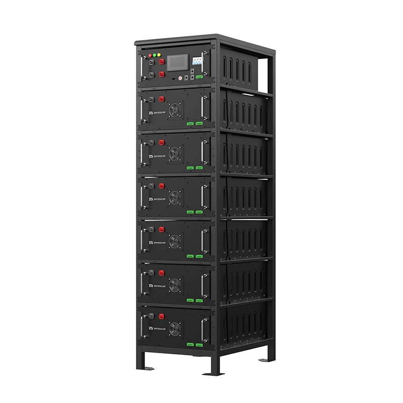
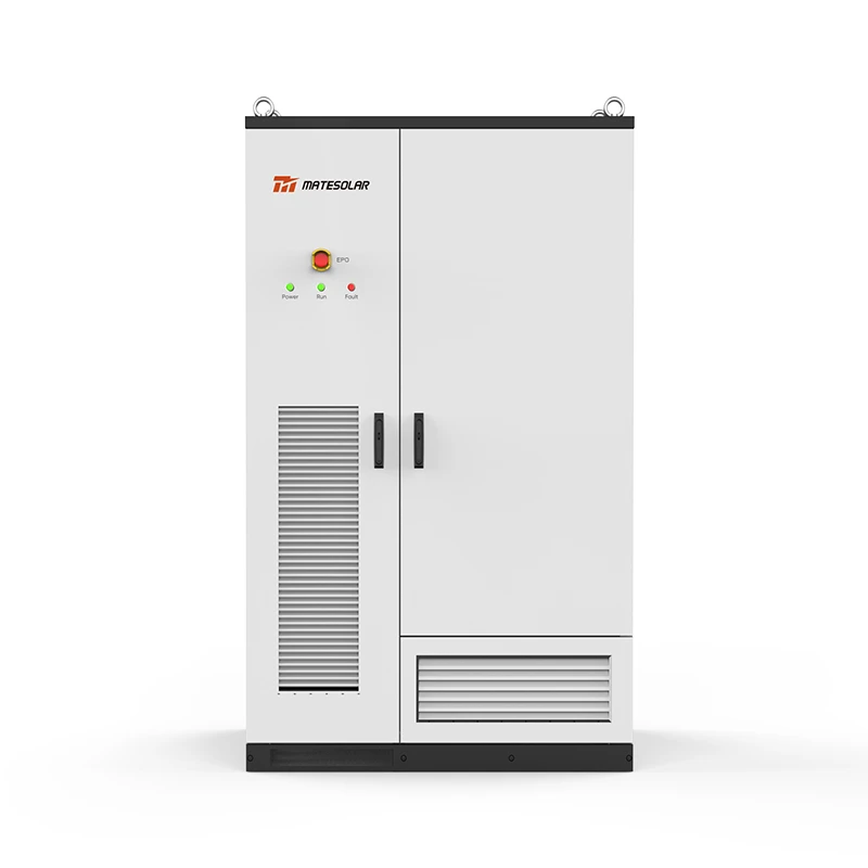
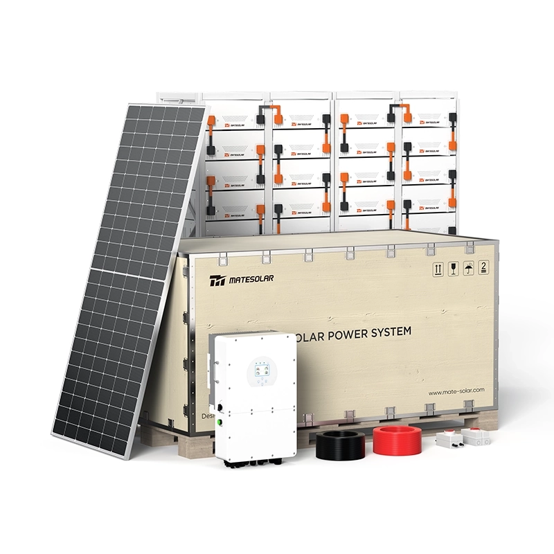
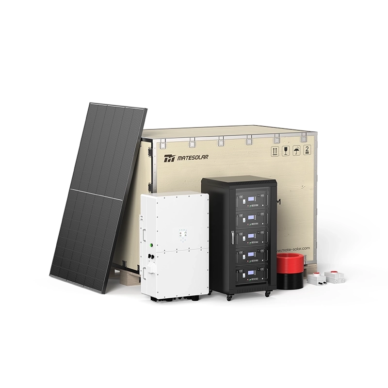
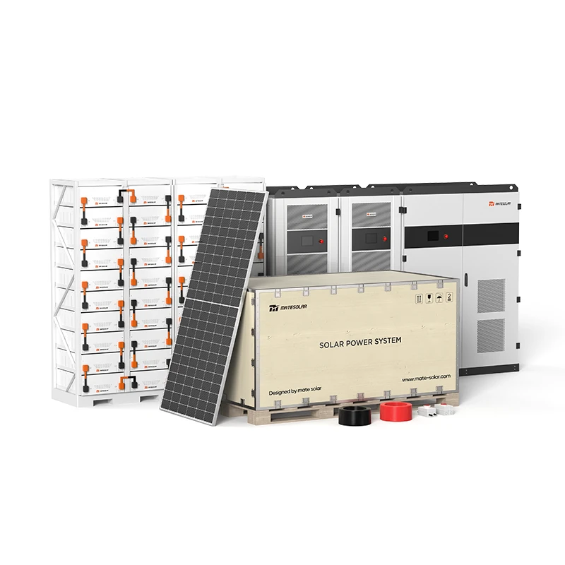
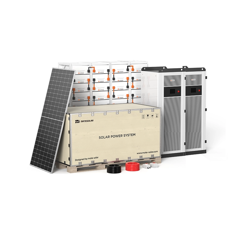
Kommerzielles 500kW Hybrid-Solarsystem
For large commercial and industrial facilities seeking comprehensive energy independence, the Commercial 500kW Hybrid Solar System combines high-efficiency PV generation with integrated battery storage. This turnkey solution is engineered for North American C&I applications, delivering:
- 500kW AC output capacity
- Integrated hybrid inverter with seamless grid/off-grid transition
- Smart energy management with demand charge optimization
- UL9540A-compliant safety systems
- Remote monitoring and control via cloud platform
To learn more about how this system can transform your facility's energy economics, visit the product page at:
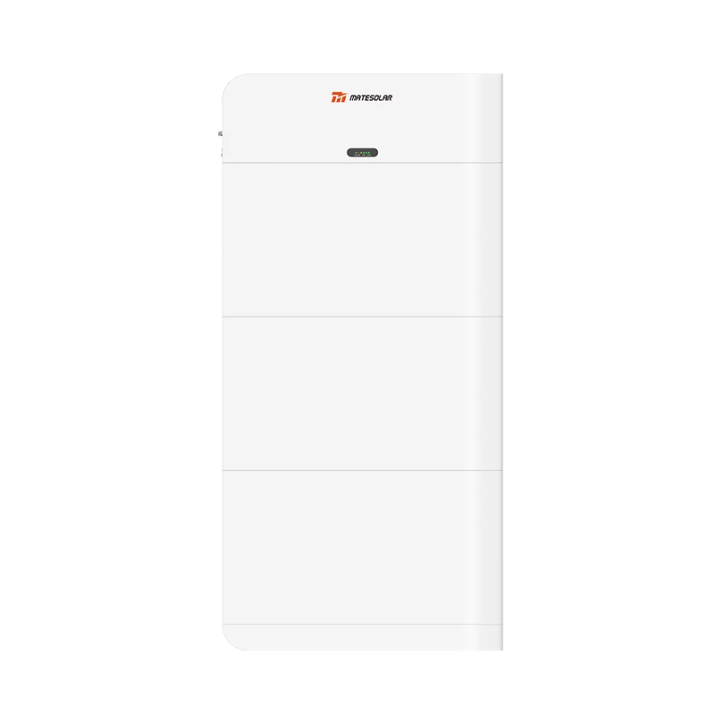
125kW/261kWh Flüssigkeitsgekühlter Outdoor-Schrank ESS
The 125kW/261kWh liquid-cooled outdoor cabinet represents the state of the art in C&I energy storage. This all-in-one solution features:
- Kapazität 261kWh DC side, 125kW AC rated output
- Kühlung Advanced liquid cooling with ±2°C cell temperature uniformity
- Fußabdruck: Compact 1.47m² design
- Battery: 314Ah LFP cells with 8,000+ cycle life
- Sicherheit UL9540A Sixth Edition compliant
- Modularity: Expandable via parallel connection
Detailed specifications and case studies are available at:
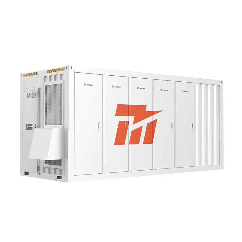
40ft 1MWh–2MWh Air-Cooled Container ESS
For larger C&I and small utility applications, the 40ft containerized ESS offers flexible capacity from 1MWh to 2MWh:
- Capacity Range: 1MWh to 2MWh
- Kühlung Intelligent air cooling with long-term stability
- Deployment: Pre-assembled and factory-tested for rapid site installation
- Modularity: Supports seamless power and energy expansion
- Anwendung: Commercial, industrial, and small utility-scale
Explore this solution further at:
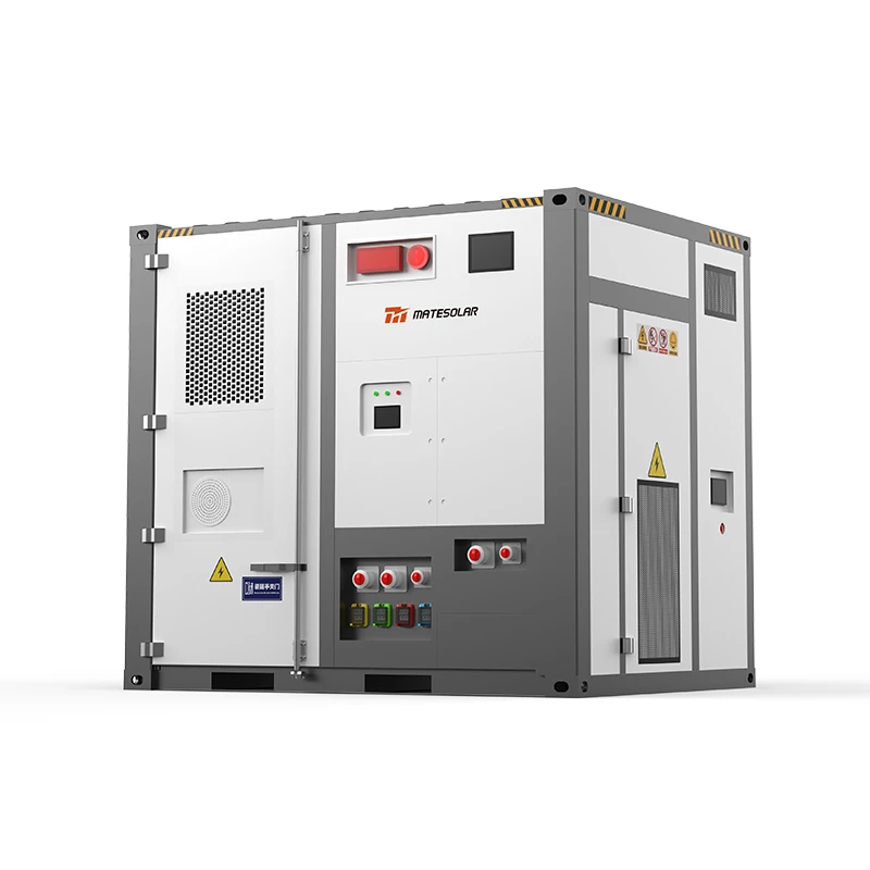
20ft 3MWh–5MWh Liquid-Cooling Container ESS
For utility-scale and large C&I applications requiring maximum energy density, the 20ft liquid-cooled container delivers 3MWh to 5MWh in a compact footprint:
- Capacity Range: 3MWh to 5MWh
- Cell Options: 280Ah and 314Ah LFP cells
- Kühlung Advanced liquid cooling for superior thermal management
- Energy Density: Industry-leading MWh per square foot
- Anwendung: Utility-scale storage, large industrial, grid services
Get full technical data and project references at:
Teil IV: Häufig gestellte Fragen
FAQ 1: What is the actual lifespan of a lithium battery storage system?
Answer: The lifespan depends on operating conditions. Under standard conditions (25°C, 80% DOD, 0.5C), LFP systems typically achieve 8,000–10,000 cycles. At one cycle per day, this translates to 22–27 years of service life. However, calendar aging (time-based degradation) typically limits useful life to 10–15 years regardless of cycle count.
FAQ 2: How do I verify a manufacturer's cycle life claim?
Answer: Require:
1. Full disclosure of test conditions (temperature, DOD, C-rate, SOH definition)
2. Third-party test reports from recognized laboratories
3. Warranty terms that align with cycle life claims
4. References from existing installations with similar operating profiles
FAQ 3: What is the difference between AC-coupled and DC-coupled storage?
Answer: In AC-coupled systems, storage connects to the AC bus through its own inverter. In DC-coupled systems, storage connects to the DC bus of a solar inverter. AC-coupled systems are more flexible (can be added to existing PV installations) and simpler to design. DC-coupled systems achieve higher round-trip efficiency (fewer conversions) but are more complex and typically only used in new installations.
FAQ 4: How much space do I need for a C&I storage system?
Answer: Space requirements have decreased significantly with liquid cooling and high-density cells. A 261kWh cabinet occupies approximately 1.5m². A 1MWh containerized system occupies approximately 25m² (including clearance). Always consult local fire codes, which may require additional spacing between units.
FAQ 5: Can I install storage without on-site technical support?
Answer: Yes, provided:
- The system is pre-assembled and factory-tested (plug-and-play design)
- Installation follows detailed documentation
- Remote commissioning and troubleshooting are available
- Hardware issues are resolved through replacement parts or unit exchange
- Software issues are addressed via remote diagnostics and updates
This model—factory pre-assembly, remote support, and component-level replacement—is increasingly standard for C&I storage systems, reducing the need for on-site technical staff.
FAQ 6: What happens if a component fails?
Answer: Under modern supply agreements:
- Hardware failures are addressed through replacement parts shipped to site, with detailed installation guides
- Major failures may result in unit exchange
- Software issues are resolved via remote technical support
- For large utility-scale projects, on-site technical support can be arranged for commissioning and debugging
FAQ 7: How does storage interact with existing solar PV?
Answer: Storage can be added to existing PV through AC coupling (connecting to the AC bus). The EMS coordinates PV generation, storage dispatch, and facility load to optimize economic outcomes. Key considerations include:
- Anti-reverse power flow protection must accommodate PV export
- Metering must separately track PV, storage, and load
- Economic optimization must consider both PV and storage revenue streams
FAQ 8: What is the payback period for C&I storage in 2026?
Answer: Payback periods vary by market but typically range from 3–7 years for C&I storage in the U.S. Key drivers include:
- Local electricity rates and demand charges
- Availability of incentives (ITC, state programs)
- System cost and performance
- Utilization rates (cycles per day)
With current ITC benefits (30% for standalone storage) and typical demand charge reductions of 20–50%, many C&I projects achieve payback within 4–5 years.
FAQ 9: What is the difference between kW and kWh in storage?
Answer: kW (kilowatts) measures power—the rate at which energy is delivered or absorbed. kWh (kilowatt-hours) measures energy—the total amount stored. A 125kW/261kWh system can deliver 125kW of power for approximately 2 hours (261 ÷ 125 ≈ 2.1 hours). Understanding this distinction is essential for sizing storage to specific applications.
FAQ 10: How do I size a storage system for my facility?
Answer: Proper sizing requires:
1. Analyse der Belastung: 12+ months of 15-minute interval load data
2. Rate analysis: Understanding tariff structure (demand charges, time-of-use rates)
3. Application definition: Peak shaving, arbitrage, backup, or combination
4. Financial modeling: Optimizing capacity against cost and revenue
5. Site assessment: Space, electrical infrastructure, permitting constraints
Part V: Technical Reference Tables
Table 1: Lithium Battery Chemistry Comparison (2026)
| Parameter | LFP | NMC | LTO | Sodium-ion |
| Energiedichte (Wh/kg) | 160–190 | 200–260 | 80–100 | 120–160 |
| Cycle Life (80% SOH) | 6,000–10,000 | 2,000–4,000 | 10,000–20,000 | 4,000–6,000 |
| Thermal Runaway Temp | >500°C | ~200°C | >500°C | >500°C |
| Cost ($/kWh) | $80–110 | $100–140 | $200–300 | $70–100 |
| Market Share (2026) | ~85% | ~8% | ~2% | ~5% |
Table 2: C&I Storage Sizing Guidelines
| Art der Einrichtung | Typical Load | Empfohlene Lagerung | Hauptanwendung |
| Retail (10,000 ft²) | 50–150 kW | 100–300 kWh | Rasierspitzen |
| Office Building (50,000 ft²) | 200–500 kW | 400–1,000 kWh | Peak shaving + arbitrage |
| Manufacturing (Small) | 300–800 kW | 600–1,600 kWh | Demand management |
| Manufacturing (Large) | 1–5 MW | 2–10 MWh | Demand management + backup |
| Rechenzentrum | 500 kW–5 MW | 1–10 MWh | Backup + power quality |
Table 3: 2026 U.S. Storage Incentive Summary
| Incentive | Bewerten | Eligibility | Status (2026) |
| ITC (Standalone Storage) | 30% | All storage | Aktiv |
| ITC (Solar+Storage) | 30% | Co-located with solar | Aktiv |
| Section 45X | Variable | Domestic manufacturing | Aktiv |
| California SGIP | Up to $0.25/Wh | C&I storage | Aktiv |
| NY-Sun | Variable | NY commercial storage | Aktiv |
| MA SMART | Variable | MA storage | Aktiv |
Table 4: Communication Protocol Selection Guide
| Protocol | Speed | Anmeldung | When to Use |
| IEC 60870-5-104 | Seconds | Grid dispatch | Always (mandatory for grid connection) |
| IEC 61850 GOOSE | Millisekunden | Fast control | Frequency regulation, grid-forming |
| MODBUS TCP | Mäßig | Device communication | Standard for PCS, BMS, meters |
| CAN | Fast | Module communication | Battery module BMS |
| 485/RS-485 | Slow | Sensors | Environmental monitoring |
Table 5: System Architecture Comparison
| Merkmal | Centralized | String/Modular | Hybrid |
| PCS per cluster | 1:N | 1:1 | 1:few |
| Wirkungsgrad | Höchste | Mäßig | Hoch |
| Verlässlichkeit | Niedrigste | Höchste | Hoch |
| Cost/kW | Niedrigste | Höchste | Mäßig |
| Skalierbarkeit | Begrenzt | Ausgezeichnet | Gut |
| Beste Anwendung | Utility-scale | C&I, microgrid | Große C&I |
Table 6: Thermal Management Performance Metrics (2026)
| Methode der Kühlung | Temp Uniformity | Parasitic Load | Wartung | Cost Premium |
| Luftkühlung | ±5°C | 2–3% | Niedrig | Base |
| Cold Plate Liquid | ±2°C | 3–5% | Mäßig | +15–25% |
| Immersion Liquid | ±1°C | 4–6% | Hoch | +40–60% |
Table 7: Key 2026 Regulatory Milestones
| Regulation / Standard | Wirksamkeitsdatum | Auswirkungen |
| GB/T 51048-2025 | April 1, 2026 | Mandates thermal runaway propagation testing |
| UL9540A Sixth Edition | March 13, 2026 | Requires Large-Scale Fire Testing (LSFT) |
| Grid-Forming Converter Standards (draft) | H2 2026 | Defines overcurrent, damping, and switching requirements |
| GB/T 43526-2023 (already in effect) | 2023 | User-side ESS technical specifications |
Part VI: 2026 Market Outlook and Strategic Implications
The AI-Driven Demand Surge
The integration of artificial intelligence and computing infrastructure with electricity systems—"computing-power-electricity synergy"—represents one of the most significant demand drivers for energy storage in the coming decade. Data centers, which require both massive power consumption and ultra-reliable supply, are increasingly turning to storage for:
- Backup power during grid disturbances
- Power quality improvement
- Participation in demand response programs
- Integration with on-site renewable generation
The National Energy Administration projects annual electricity demand growth of approximately 600 billion kWh during the "15th Five-Year Plan" period, driven significantly by computing and AI demand.
The Grid-Forming Transition
As renewable penetration continues to increase, the transition from grid-following to grid-forming storage is accelerating. By 2026, grid-forming capability is transitioning from a differentiator to a requirement for many grid-connected applications. The pending national standards for grid-forming converters will establish clear performance requirements and test methodologies.
The Safety Imperative
The sixth edition of UL9540A, with its mandatory Large-Scale Fire Testing requirement, represents a step-change in storage safety standards. Projects that cannot demonstrate system-level fire propagation prevention will face regulatory barriers, insurance challenges, and financing difficulties. This is particularly critical in the North American market, where UL9540A certification has become a de facto requirement for project bankability.
The Profitability Equation
The transition from policy-driven to market-driven deployment means that storage projects must now stand on their own economic merits. Successful projects in 2026 and beyond will:
1. Optimize for multiple revenue streams (arbitrage, demand charge reduction, ancillary services)
2. Achieve system-level RTE above 88%
3. Maintain high availability (>98%)
4. Demonstrate bankable safety certifications
5. Leverage intelligent EMS for real-time optimization
Regional Focus: North America and Central America
For the North American market, the combination of ITC incentives, high electricity costs, and growing grid instability creates a compelling environment for C&I storage deployment. The U.S. market alone is projected to install 70 GWh in 2026, with C&I applications representing a growing share. Central American markets (excluding Cuba and Mexico) are also showing strong growth, driven by rising industrial demand and improving regulatory frameworks.
MateSolar's product portfolio is specifically designed to meet the requirements of these markets, with UL9540A Sixth Edition certification, 60 Hz / 480V AC output compatibility, and remote support infrastructure that eliminates the need for local installation teams. Our systems are shipped fully pre-assembled and factory-tested, requiring only civil works and electrical connections on site. Hardware issues are resolved through replacement parts with detailed installation guides, or through unit exchange for major failures. Software problems are handled via remote diagnostics and over-the-air updates. For large utility-scale projects, we can dispatch technical personnel for on-site commissioning and debugging upon request.
Conclusion: Mastery in the Age of Storage
The energy storage industry has entered its maturity phase. The era of easy policy-driven deployment is over; the era of market-driven performance has arrived. For professionals in this field, mastery of the technical, operational, and commercial dimensions of lithium battery storage is no longer optional—it is the foundation of professional credibility and commercial success.
The 18 knowledge domains covered in this compendium represent the essential toolkit for navigating the 2026 storage landscape:
- Technical fundamentals (cycle life, RTE, balancing, cooling)
- Safety and certification (UL9540A, fire protection)
- Application knowledge (energy vs. power cells, grid-forming)
- Systemdesign (architecture selection, voltage selection, anti-reverse protection)
- Integration (solar+storage, communications)
- Economics (demand management, revenue optimization)
Those who master these domains will be positioned to lead in an industry projected to reach USD. trillion in global market size by 2030. Those who do not will find themselves increasingly marginalized in a sector that demands ever-higher levels of technical and commercial sophistication.
This compendium was prepared on July 7, 2026, reflecting the most current market data, technical standards, and regulatory developments available at the time of publication. The energy storage industry evolves rapidly; readers are encouraged to verify specific technical specifications and regulatory requirements for their particular applications and jurisdictions.
Über MateSolar
MateSolar is a premier one-stop photovoltaic and energy storage solution provider, delivering comprehensive solar-plus-storage systems for commercial, industrial, and utility-scale applications. With a product portfolio spanning from 125kW/261kWh liquid-cooled outdoor cabinets to 5MWh containerized ESS platforms, MateSolar combines advanced LFP battery technology, intelligent energy management, and bankable safety certifications (UL9540A Sixth Edition compliant) to deliver turnkey solutions that maximize energy cost savings and operational reliability.
Our commitment extends beyond hardware delivery: we provide remote commissioning support, software troubleshooting, and component-level replacement logistics for hardware issues—ensuring that our customers receive world-class support regardless of geographic location. For large-scale projects, on-site technical support is available for commissioning and debugging upon request.
Partner with MateSolar—where innovation meets reliability in the energy storage revolution.