










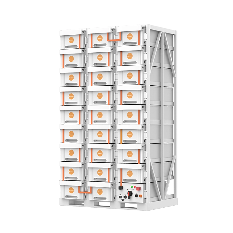
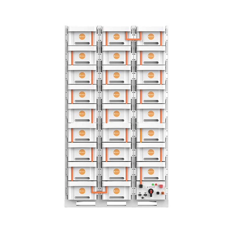
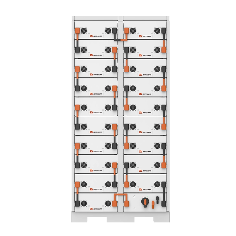
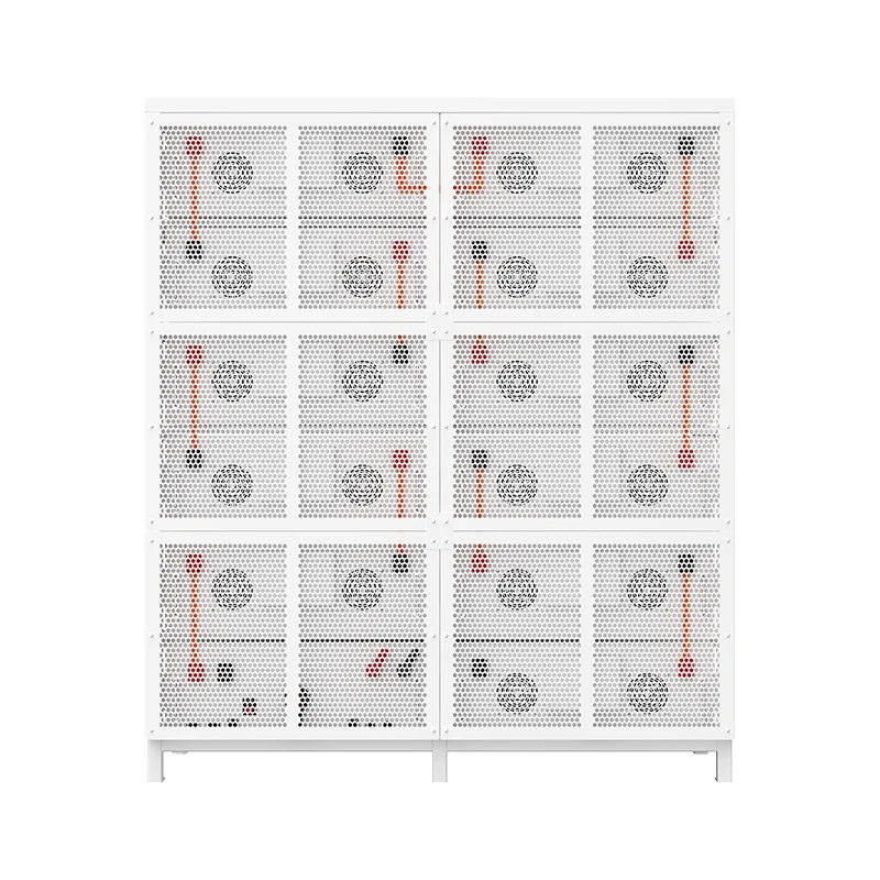







Executive Summary: Die Billionen-Dollar-Transformation
Die Energiespeicherbranche hat im Jahr 2026 eine historische Schwelle überschritten. Der Energiespeicher ist nicht mehr nur ein politisch motivierter Anhang zu Projekten im Bereich der erneuerbaren Energien, sondern hat sich zu einem marktorientierten, billionenschweren Ökosystem entwickelt, das weltweit das strukturelle Rückgrat moderner Stromversorgungssysteme bildet. Die weltweit kumulierte installierte Energiespeicherkapazität erreichte bis Ende 2025 277,7 GW / 679,6 GWh, wobei die jährlichen Zuwächse von 112,5 GW / 310,6 GWh einem Wachstum gegenüber dem Vorjahr von 51,61 TP3T bzw. 77,51 TP3T entsprechen. Die Prognose für 2026 fällt sogar noch ehrgeiziger aus: Analysten gehen weltweit von 265 GWh an Neuinstallationen aus, was einem Anstieg von 63% gegenüber 2025 entspricht.
Was diesen Moment von früheren Wachstumszyklen unterscheidet, ist ein fundamentaler Wandel in der Betriebslogik der Branche. Der Markt hat sich von der politisch verordneten Bereitstellung hin zur marktorientierten Rentabilität verlagert. Das Dokument Nr. 136 schaffte die Pflichtspeicherzuweisungsanforderungen für neue erneuerbare Energieprojekte ab und zwang die Branche, auf eigenen wirtschaftlichen Füßen zu stehen. Gleichzeitig führte das Dokument Nr. 114 einen nationalen Kapazitätsvergütungsmechanismus ein, der eine nachhaltige Einnahmequelle für Speicheranlagen schuf. Die erstmalige Aufnahme von "Synergien zwischen Rechenleistung und Strom" in den Berichten der Regierung über die Arbeit signalisiert, dass das explosive Wachstum von KI und der Bedarf an Rechenzentren über Jahre hinweg ein struktureller Treiber für den Ausbau von Speichern sein wird.
Für Fachleute, die im Bereich der Energiespeicherung tätig sind – seien es Entwickler, Ingenieure, Finanzierer oder Systembetreiber – ist das Verständnis der technischen Feinheiten, Marktdynamiken und betrieblichen Realitäten von Lithiumbatterie-Energiespeichersystemen (BESS) keine Option mehr. Es ist die Eintrittsgebühr für einen Sektor, dessen Investitionshöhe laut Prognose der Nationalen Energieverwaltung allein während des "15. Fünfjahresplans" über 2 Billionen RMB betragen wird.
Dieses Kompendium destilliert die 18 kritischsten Wissensgebiete im Bereich der Lithium-Ionen-Batteriespeicherung, basierend auf den neuesten Standards von 2026, Marktdaten und technischen Spezifikationen. Beherrschen Sie zehn davon und Sie sind ein echter Branchenkenner. Beherrschen Sie alle achtzehn, und Sie sind gerüstet, um im dynamischsten Energiesektor des Jahrzehnts führend zu sein.
Teil I: Marktkontext – Die Landschaft im Jahr 2026
Bevor wir uns mit technischen Spezifikationen befassen, ist es wichtig, die Marktkräfte zu verstehen, die die Branche Mitte 2026 prägen.
Die Nordamerikanische Chance
Die Vereinigten Staaten bleiben außerhalb Chinas der bedeutendste Markt für Energiespeicher im Gewerbe- und Industriebereich (C&I). Im Jahr 2025 wurden in den USA neue Batteriespeicherkapazitäten in Rekordhöhe von 57 GWh installiert, was einem Anstieg von 29% gegenüber dem Vorjahr entspricht. Prognosen zufolge wird die Branche im Jahr 2026 weitere 70 GWh hinzufügen, wobei bis 2030 fast 500 GWh im Netz erwartet werden. Der nordamerikanische BESS-Markt wurde im Jahr 2025 auf 20,82 Milliarden US-Dollar geschätzt und soll bis 2031 49,34 Milliarden US-Dollar erreichen, was einer durchschnittlichen jährlichen Wachstumsrate von 15,48% entspricht.
Die politischen Rahmenbedingungen sind nach wie vor äußerst günstig. Die Investitionssteuergutschrift (Investment Tax Credit, ITC) für eigenständige Energiespeicher bietet in Verbindung mit der Produktionsgutschrift für fortschrittliche Fertigung gemäß Section 45X und den Bonuszahlungen für inländische Komponenten starke finanzielle Anreize. Kaliforniens NEM-3.0-Regelung, die die Einspeisevergütung für Dachsolaranlagen um etwa 75% gekürzt hat (wobei für überschüssige Energie nur noch 2–3 Cent pro kWh gezahlt werden), hat überzeugende wirtschaftliche Argumente für die gemeinsame Installation von Speichersystemen geliefert. Texas hat, angetrieben von der Marktdynamik des ERCOT und der Nachfrage nach KI-Rechenzentren, Kalifornien als größten regionalen Speichermarkt in den USA überholt.
Von Volumen zu Wert
Die Wettbewerbsdynamik der Branche hat sich entschieden verschoben. Nach brutalen Preiskämpfen, die die Systempreise zwischen 2023 und 2025 von 1,2 RMB/Wh auf unter 0,6 RMB/Wh gedrückt haben, ist der Markt von 2026 durch einen Wettbewerb um den **Gesamtwert über den gesamten Lebenszyklus** und nicht mehr um die Anschaffungskosten geprägt. Die führenden Akteure differenzieren sich durch:
- Großformatige Zelltechnologie (314 Ah und darüber hinaus)
- Fortschrittliches Wärmemanagement (Flüssigkeitskühlung wird zum Standard)
- Intelligente Betriebsführung und Instandhaltung (KI-gestützte prädiktive Analytik)
- Überlegene Sicherheitszertifizierungen (konform mit UL9540A sechste Ausgabe)
Die Marktkonzentration hat sich verstärkt, wobei die fünf führenden Batteriehersteller mittlerweile einen Marktanteil von über 65% halten. Systemintegratoren sehen sich einem ähnlichen Konsolidierungsdruck ausgesetzt, da die Auftragsbücher der führenden Akteure bereits bis in die zweite Hälfte des Jahres 2026 gefüllt sind.
Teil II: Die 18 wesentlichen Wissensgebiete
Wissenspunkt 1: Die Wahrheit hinter "8.000 Zyklen"-Bewertungen
Die Frage, die jeder Käufer stellen muss
Wenn ein Hersteller bei seinem Energiespeichersystem mit "8.000 Zyklen" wirbt, ist diese Zahl bedeutungslos, ohne die zugrunde liegenden Bedingungen zu verstehen. Die Standardangabe von 8.000 Zyklen basiert auf drei spezifischen Bedingungen:
| Parameter | Standardbedingung | Realitätscheck |
| Zelltemperatur | 25°C (77°F) | Die reale Temperatur schwankt erheblich |
| Entladetiefe (DOD) | 100% | Die meisten Systeme arbeiten mit einem DOD von 80–90%. |
| Gesundheitszustand | 80% | Manche definieren EOL als 70% |
Die drei Verhöre:
1. Temperaturregelung Kann der Hersteller Zelltemperaturunterschiede garantieren, die alle Zellen nahe 25°C halten? Flüssigkeitskühlsysteme erreichen typischerweise eine Gleichmäßigkeit von ±2°C; luftgekühlte Systeme können ±5°C oder mehr aufweisen. Jede 10°C über 25°C können die Lebensdauer der Batterie halbieren.
2. DOD-Berechnung Wenn die Angabe von 8.000 Zyklen auf einem DOD von 100% basiert, Ihr System jedoch mit einem DOD von 90% betrieben wird, wie rechnet der Hersteller dann die Nennleistung um? Entscheidend ist dabei die Frage, ob die Berechnung auf der Grundlage von Energie aufladen oder Energie entladenDa Ladungs-/Entladungsverluste bestehen, stellen entladungsbasierte Berechnungen eine genauere Darstellung der nutzbaren Energie über die Lebensdauer des Systems dar.
3. Definition des Lebensendes: Wird das EOL bei einem SOH-Wert von 80% oder 70% definiert? Der Unterschied ist erheblich – ein System, das bei einem SOH-Wert von 80% 8.000 Zyklen erreicht, könnte bei einem SOH-Wert von 70% mehr als 10.000 Zyklen erreichen. Einige Hersteller verwenden 70%, um ihre Angaben zur Zyklenlebensdauer attraktiver zu gestalten; andere nutzen 80% als konservativeren und branchenüblichen Maßstab.
Branchenbestprates Fordern Sie, dass Angaben zur Zyklenlebensdauer von vollständigen Offenlegungen der Testbedingungen begleitet werden, einschließlich Temperaturprofilen, Annahmen zum DOD (Tiefentladung), der Definition von SOH (Zustand der Gesundheit) und der spezifischen C-Rate, die während des Tests verwendet wurde.
Wissenspunkt 2: Round-Trip-Effizienz (RTE) – Die wahre Rentabilitätskennzahl
Der Round-Trip-Wirkungsgrad ist die wichtigste finanzielle Kennzahl für jedes Energiespeichersystem. RTE = Entladene Energie ÷ Geladene Energie. Ein System mit einem RTE-Wert von 90% liefert pro 10 kWh geladener Energie 9 kWh zurück. Der Unterschied zwischen einem RTE-Wert von 85% und 92% kann über die gesamte Projektlaufzeit hinweg zu Einnahmeverlusten in Millionenhöhe führen.
Die versteckten Verluste, über die die meisten Hersteller nicht sprechen:
| Verlustkategorie | Typischer Bereich | Oft übersehen? |
| PCS-Umwandlung (DC-AC / AC-DC) | 1–31 TP3T pro Strecke | Nein |
| Batterieinnenwiderstand | 2–5% | Nein |
| Hilfsverbraucher (Kühlung, BMS, Regelung) | 3–8% | Ja |
| Kabel- und Verbindungspunktverluste | 1–2% | Ja |
| Systemausfall / Störungen | Variable | Ja |
Viele Hersteller zitieren RTE ausschließlich basierend auf PCS-Eingangs-zu-Ausgangsmessungen, ausgenommen:
- Stromverbrauch des Flüssigkeitskühlsystems (kann in heißen Klimazonen 3–51 TP3T der Nennleistung betragen)
- Schaltschrank Eigenverbrauch (BMS, Überwachung, Kommunikation)
- Transformatoren- und Kabelverluste
- Degradation im Laufe der Zeit
Der Standard 2026: Führende Anbieter bieten mittlerweile "RTE-Garantien auf Systemebene" an, die am Netzanschlusspunkt gemessen werden und alle parasitären Lasten berücksichtigen. Bei Lithium-Eisenphosphat-Systemen (LFP) liegt die erreichbare RTE auf Systemebene in der Regel zwischen 85% und 92%, abhängig von den Betriebsbedingungen und der C-Rate.
Kritische Frage: Wird die RTE-Angabe des Herstellers durch Tests von Drittanbietern unter repräsentativen Betriebsbedingungen, einschließlich des Verbrauchs von Hilfsaggregaten, validiert?
Wissenspunkt 3: Brandschutz – Der Dreistufige Schutzrahmen
Der thermische Durchgehen bleibt das existenzielle Risiko für Energiespeicher mit Lithiumbatterien. Ein robustes Brandschutzsystem muss auf drei verschiedenen Ebenen funktionieren:
| Ebene | Umfang | Schutzmechanismus |
| Level 1: Pack-Level | Individuelle Batteriemodule | Gasdetektion, Aerosolunterdrückung, thermische Überwachung auf Zellebene |
| Level 2: Rack-/Cluster-Ebene | Batterieracks innerhalb eines Schranks | Wasserminne oder Gaslöschanlagen, Trennschütze |
| Ebene 3: Systemebene | Gesamter Behälter oder Gehäuse | Raum-/Behälterflutung, Fernüberwachung, Notentlüftung |
Der Realitätscheck: Viele Hersteller werben mit "dreistufigem Schutz", liefern aber nur ein oder zwei funktionale Stufen. Übliche Taktiken umfassen:
- Spezifizierung der Aerosolunterdrückung auf Pack-Ebene, aber Weglassen des Rack-Schutzes
- Kombination von Rack- und Systemebene zu einer einzigen Unterdrückungszone
- Bereitstellung von Erkennung ohne aktive Unterdrückung bei bestimmten Stufen
Der Standard 2026: GB/T 51048-2025 (in Kraft getreten am 1. April 2026) schreibt Berichte über thermische Durchgehensprüfungen für großflächige Speicherprojekte vor. Systeme, die keine wirksame Verhinderung der Ausbreitung nachweisen können, sehen sich erheblichen regulatorischen und versicherungstechnischen Hürden gegenüber.
Wissenspunkt 4: UL9540A – Die Sicherheitszertifizierung, die Projekte ermöglicht oder scheitern lässt
UL9540A ist der strengste und weltweit anerkannteste Standard zur Bewertung der Brandfortleitung bei thermischem Durchgehen in Batteriespeichersystemen. Es ist nicht nur eine reine Konformitätsübung – es ist eine Voraussetzung für die Finanzierbarkeit von Projekten in Nordamerika und zunehmend auch weltweit.
Was UL9540A-Tests:
- Ob sich ein thermisches Durchgehen in einer Zelle auf benachbarte Zellen ausbreitet
- Ob sich Feuer von einem Modul auf das nächste ausbreitet
- Ob ein ganzer Rack oder Container betroffen ist
- Ob Feuer zwischen angrenzenden Behältern oder Strukturen überspringt
Die Revolution der Sechsten Edition: Am 13. März 2026 veröffentlichte ULSE offiziell die sechste Ausgabe der UL9540A:2026. Die bedeutendste Änderung ist die verpflichtende Aufnahme von Großangelegte Brandversuche (LSFT) auf der Installationsebene. Dieser Test beinhaltet:
- Deaktivierung aller Brandunterdrückungs- und Brandmeldesysteme
- Eine vollständige Energiespeichereinheit zünden
- Brandfortschritt auf benachbarte Einheiten beobachten
Die LSFT-Anforderung bedeutet, dass Systeme nun eine Brandsicherheit auf Systemebene nachweisen müssen, nicht nur eine Leistung auf Zell- oder Modulebene. Hersteller müssen nachweisen, dass sich Feuer nicht zwischen Einheiten ausbreitet – ein weitaus anspruchsvollerer Standard als in früheren Ausgaben.
Praktische Implikation: Für gewerbliche und industrielle Projekte in den USA ist ein UL9540A-Bericht jetzt ein nicht verhandelbare Voraussetzung für:
- Baugenehmigungen einholen
- Versicherungsschutz sichern
- Übergreifende Anforderungen an die Netzintegration von Versorgungsunternehmen
- Projektrealisierung durch Finanzierung
Ohne UL9540A-Zertifizierung können Ihre Speichergeräte möglicherweise nicht installiert, nicht versichert und nicht finanziert werden.
Wissenpunkt 5: Energiezellen vs. Stromzellen – Eine Größe passt nicht für alle
Die vorherrschende Annahme, dass "alle Lithium-Batteriezellen im Wesentlichen gleich sind", ist gefährlich falsch. Die Anforderungen an die Zellen für die Energiearbitrage (Peak Shaving, Verschiebung der Nutzungszeit) unterscheiden sich grundlegend von denen für Netzdienstleistungen (Frequenzregelung, Hilfsdienste).
| Parameter | Energiezellen (0,25–0,5C) | Energiezellen (1C–3C) |
| Hauptanwendung | Lastspitzenkappung, Arbitrage | Frequenzregelung, Netzunterstützung |
| Entladedauer | 2-4 Stunden | 15 Minuten – 1 Stunde |
| Pulsfähigkeit | Niedrig | Hoch |
| Wärmeerzeugung | Mäßig | Hoch |
| Zyklenlebensdauer bei 1C | 8,000+ | 4,000–6,000 |
| Kosten pro kWh | Unter | Höher |
Energie Zell Eigenschaften:
- Optimiert für hohe Energiedichte und lange Entladezeit
- Schlechte Pulsleistung – kann nicht schnell auf Frequenzabweichungen reagieren
- Ein hoher Innenwiderstand führt zu einem signifikanten Spannungsabfall bei hohen C-Raten
- Schneller Abbau bei häufigem Zyklieren mit hoher Rate
Leistungsmerkmale der Zelle:
- Optimiert für hohe Leistungsdichte und schnelle Reaktion
- Kann Millisekunden-Reaktionszeiten für die Frequenzregelung liefern
- Geringere Energiedichte; höhere Kosten pro kWh
- Besseres Wärmemanagement aufgrund höherer Wärmeentwicklung erforderlich
Der kritische Fehler: Die Verwendung von Energiezellen in Frequenzregelanwendungen führt zu schnellem Kapazitätsverlust, Herausforderungen im Wärmemanagement und schlechter Leistung bei Netzservicekennzahlen. Die Verwendung von Leistungzellen in Energiespeicheranwendungen zerstört die wirtschaftliche Grundlage durch überhöhte Kapitalkosten.
2026 Trend: Die Industrie bewegt sich in Richtung "Dual-Use"-Zellen, die beide Funktionen mit akzeptabler Leistung ausführen können, aber eine echte Optimierung erfordert immer noch die anwendungsspezifische Zellenauswahl.
Wissenspunkt 6: Strategien für die Bilanz – Passiv vs. Aktiv
Innerhalb jedes Batteriespeichersystems weichen die Zellen zwangsläufig aufgrund von Fertigungsschwankungen, Temperaturgradienten und unterschiedlicher Alterung in ihrer Leistung voneinander ab. Ohne effektives Balancing verstärken sich diese Abweichungen, reduzieren die nutzbare Kapazität und bergen Sicherheitsrisiken.
| Typenausgleich | Mechanismus | Vorteile | Benachteiligungen |
| Passivausgleich | Resistive Ableitung von überschüssiger Energie | Einfach, kostengünstig | Verschwendet Energie, erzeugt Wärme, langsam |
| Aktives Balancing (BMU-Ebene) | DC/DC-Übertragung zwischen Zellen innerhalb eines Moduls | Effizienter als passiv | Komplex, höhere Kosten |
| Aktives Balancing (Cluster-Ebene) | DC/DC auf Rack-Ebene | Wirksam im gesamten Cluster | Höhere Systemkosten |
| Aktives Balancing (EMS-gesteuert) | Bereichsbezogene Steuerung einzelner Cluster | Höchste Flexibilität, höchste Effizienz | Erfordert eine ausgefeilte EMS/BMS-Integration |
Passivausgleich verwendet Widerstände, um überschüssige Energie von Zellen mit höherer Spannung zu verbrauchen, bis alle Zellen übereinstimmen. Dieser Ansatz ist für kleine Systeme (Wohngebäude, kleine Gewerbebetriebe) akzeptabel, ist jedoch für die großtechnische Speicherung aufgrund des Energieverlusts und der Herausforderungen im Wärmemanagement unpraktikabel.
Aktives Auswuchten überträgt Energie von Zellen mit höherer Ladung auf Zellen mit niedrigerer Ladung, wodurch die Energie erhalten bleibt. Drei Hauptansätze dominieren den Markt 2026:
1. BMU-integriertes DC/DC: Jede Batteriemanagementeinheit enthält DC/DC-Wandler, die Energie zwischen Zellen innerhalb eines Moduls bewegen. Effektiv, aber erhöht Kosten und Komplexität.
2. Rack-Level-DC/DC Ein DC/DC-Wandler auf Rack-Ebene ermöglicht den Ausgleich über einen gesamten Batteriestrang. Dieser Ansatz behebt die fehlerhafte Abstimmung auf Cluster-Ebene, die durch die Abstimmung auf BMU-Ebene nicht gelöst werden kann.
3. EMS-gesteuerte Cluster-Balance: Das standortweite Energiemanagementsystem koordiniert die Steuerung über Cluster und sogar einzelne Speicherpakete hinweg und befiehlt unterschiedliche Lade-/Entladeströme, um ein Gleichgewicht zu erreichen. Dieser Ansatz erfordert die höchste Integrationsstufe zwischen EMS und BMS, liefert aber die besten Ergebnisse.
2026 Best Practice: Für Systeme über 1 MWh wird das aktive Balancing auf Modul- und Clusterebene zunehmend zum Standard. EMS-gesteuertes Cluster-Balancing wird zum Unterscheidungsmerkmal zwischen Premium- und Commodity-Systemen.
Wissenspunkt 7: Flüssigkeitskühlung – Kaltplatte vs. Immersion
Mit steigender Energiedichte und der Skalierung von Systemen auf Multi-MWh-Kapazitäten ist das Thermomanagement zu einem entscheidenden Unterscheidungsmerkmal im Design geworden. Flüssigkeitskühlung hat die Luftkühlung in großen Stromversorgungsanlagen und großen C&I-Anwendungen weitgehend abgelöst.
| Parameter | Kühlplatte (indirekt) | Immersion (Direkt) |
| Kühlmedium | Kühlmittel in Metallplatten | Dielektrikum, das Zellen umgibt |
| Kontakt | Indirekt (Platte bis Zelle) | Direkt (Flüssigkeit zur Zelloberfläche) |
| Wirkungsgrad der Wärmeübertragung | Gut | Ausgezeichnet |
| Gleichmäßigkeit der Temperatur | ±2°C typisch | ±1°C erreichbar |
| Systemkosten | Unter | Höher |
| Komplexität der Wartung | Mäßig | Hoch |
| Leckrisiko | Mäßig | Hoch |
| Marktanteil (2026) | ~85% | ~15% |
Kaltwasserplatten Flüssigkühlung bleibt der dominante Ansatz für 2026:
- Ausgereifte, gut verstandene Technologie
- Geringere Kapitalkosten
- Akzeptable thermische Leistung für die meisten Anwendungen
- Einfacher zu warten und zu reparieren
Flüssigkeitskühlung durch Immersion gewinnt in Hochleistungsanwendungen an Boden:
- Überlegene Wärmeableitung ermöglicht höheren C-Raten-Betrieb
- Außergewöhnliche Temperaturhomogenität verlängert die Lebensdauer von Zellen
- Bietet eine intrinsische Brandunterdrückung (Dielektrikum ist nicht brennbar)
- Höhere Kapitalkosten und komplexere Wartung
Die Entscheidung 2026: Für Standardanwendungen im Bereich Regelung und Steuerung (0,5C, 2 Stunden Dauer) ist die Flüssigkühlung über Kaltplatten die eindeutig wirtschaftlichere Wahl. Für Hochleistungsanwendungen (1C+ Frequenzregelung, extreme Klimazonen) bietet die Tauchkühlung überzeugende Vorteile, die den Aufpreis rechtfertigen.
Wissenspunkt 8: Externe Kommunikation — Die Standards 104 und 61850
Energiespeichersysteme müssen mit zwei primären externen Einheiten kommunizieren: Netzleitstellen und virtuelle Kraftwerke (VPPs). Die Wahl des Kommunikationsprotokolls bestimmt die Systeminteroperabilität, die Reaktionsgeschwindigkeit und die Netzkonformität.
| Protokoll | Anmeldung | Geschwindigkeit | Hauptverwendungszweck |
| IEC 60870-5-104 | Netzdispatch (China, international) | Sekunden | Telemetrie, Fernsteuerung, AGC/AVC |
| IEC 61850 (MMS/GOOSE/SV) | Intelligentes Stromnetz, Hochgeschwindigkeitsanwendungen | Millisekunden | Schnellsteuerung, Schutzkoordination |
IEC 60870-5-104 (104-Protokoll) :
- Das vorgeschriebene Protokoll für den Netzdispatch in China und vielen internationalen Märkten
- TCP/IP-basiert (Port 2404)
- Unterstützt Telemetrie (Messungen), Fernsteuerung (Befehle) und AGC/AVC-Dispatch
- Angemessen für die meisten Energiearbitrage- und Spitzenlastausgleichsanwendungen
IEC 61850 :
- Erforderlich für Hochgeschwindigkeitsanwendungen, bei denen eine Reaktionszeit von unter einer Sekunde entscheidend ist
- GOOSE (Generic Object Oriented Substation Event) ermöglicht Kommunikation auf Millisekundenbasis
- SV (Sampled Values) ermöglicht die Echtzeit-Weitergabe von Messwerten
- Unerlässlich für die Frequenzregelung und netzbildende Anwendungen
2026 Best Practice: Die meisten modernen Systeme unterstützen beide Protokolle, wobei 104 die Verteilung und Telemetrie und 61850 die schnelle Regelung und Schutzzkoordination übernimmt.
Wissenpunkt 9: Interne Kommunikation – Die Protokolllandschaft
Innerhalb eines Speichersystems müssen mehrere Geräte über unterschiedliche Protokolle kommunizieren. Der Systemcontroller (oft als Energiespeichersteuereinheit bezeichnet) übernimmt die Protokollkonvertierung und Aggregation.
| Protokoll | Hauptverwendungszweck | Geschwindigkeit |
| MODBUS TCP | PCS, BMS, Zählerkommunikation | Mäßig |
| MODBUS RTU | Serielle Gerätekommunikation | Langsam |
| CAN | Interne Akkermodulkommunikation | Schnell |
| 485 / RS-485 | Messung, Umweltsensoren | Langsam |
| IoT-Protokolle | Cloud-Überwachung, Ferndiagnose | Variable |
MODBUS bleibt aufgrund seiner Einfachheit und weit verbreiteten Unterstützung das Arbeitstierprotokoll für die industrielle Kommunikation in Speichersystemen.
CAN (Controller Area Network) ist der Standard für die Kommunikation zwischen BMS und einzelnen Batteriemodulen und bietet die für die Zellüberwachung erforderliche Geschwindigkeit und Zuverlässigkeit.
2026 Trend: Die Industrie bewegt sich schrittweise in Richtung standardisierter Kommunikationsarchitekturen, die die Anzahl der Protokollkonvertierungen reduzieren, die Zuverlässigkeit verbessern und die Latenz verringern.
Wissenspunkt 10: Netzkopplungsspannung – Das richtige Niveau anpassen
Die Auswahl der richtigen Netzanschlussspannung ist eine kritische Designentscheidung, die Kosten, Genehmigungsverfahren und die Machbarkeit des Projekts beeinflusst.
| System Skala | Empfohlene Spannung | Maßgebender Standard |
| <1 MW (Eigenverbrauch) | 380V / 480V | GB/T 43526-2023 |
| 1–10 MW (Gewerbe- & Industriestandorte) | 10 kV / 12,47 kV | GB/T 43526-2023 |
| 10 MW oder Netzdienstleistungen | 35 kV+ | GB/T 36547-2024 |
| Unabhängiger Speicher | 10 kV+ (variiert) | Volle Netzkonformität |
Schlüsselfaktoren:
1. Kapazitätsschwellenwerte: Die meisten Energieversorger haben vereinfachte Anschlussverfahren für Anlagen unterhalb bestimmter Kapazitätsschwellen. Das Überschreiten dieser Schwellen löst komplexere und kostspieligere Studien aus.
2. Bestehende Infrastruktur Die vorhandene Transformator- und Schaltanlagenkapazität der Anlage kann die Anschlussmöglichkeiten einschränken.
3. Versorgungsanforderungen: Verschiedene Versorgungsunternehmen haben unterschiedliche Standards für Schutz, Messung und Kommunikation auf verschiedenen Spannungsebenen.
2026 Best Practice: Führen Sie eine vollständige Machbarkeitsstudie für die Netzintegration durch, bevor Sie die Spannungsebenen auswählen. Der Kostenunterschied zwischen einer 480-V- und einer 10-kV-Netzanbindung kann erheblich sein, aber die falsche Wahl kann ein Projekt in regulatorisches Fegefeuer stürzen.
Wissenpunkt 11: Warum sollte die Spannung der Stromnetzverbindung von der Spannung des Betriebsnetzes abweichen
Ein häufiger Fehler bei C&I-Speicherprojekten ist der Versuch, auf der gleichen Spannungsebene wie die Hauptversorgung des Standorts zu verbinden. Dies führt zu erheblichen technischen und regulatorischen Herausforderungen.
Das Problem der gleichspannungsgebundenen Verbundsysteme:
1. Genehmigungskomplexität von Versorgungsunternehmen Die Verbindung mit der gleichen Spannung wie die Stromversorgung des Betriebs erfordert oft die Genehmigung des Energieversorgers für den gesamten Transformator, nicht nur für das Speichersystem. Dies löst langwierige und unsichere Prüfverfahren aus.
2. Lastgitter-Wirkung: Die Gleichspannungsverschaltung kann die Spitzenlastzahlungen erhöhen, da die Ladeleistung des Speichersystems während der Nebenlastzeiten auf dem Stromzähler des Versorgungsunternehmens erscheint.
3. Schutzkoordination Schutzkonzepte werden komplexer, wenn der Speicher auf derselben Spannungsebene wie die Hauptspeisung angeschlossen ist.
4. Messkomplikationen: Die Unterscheidung zwischen Anlagenlast und Lade-/Entladeleistung von Speichern erfordert eine anspruchsvollere Messtechnik.
Die Lösung: Niederspannungs-Anbindung (z. B. 480V für eine Anlage mit 10kV-Anschluss). Dies vereinfacht die Genehmigung durch den Netzbetreiber, ermöglicht eine klare Zählertrennung und reduziert die Komplexität der Schutzkoordination.
Wissenspunkt 12: Cross-Transformer-Verbrauch
In Anlagen mit mehreren parallel geschalteten Transformatoren ermöglicht der transfomatorübergreifende Verbrauch eine effizientere Nutzung der Speicherkapazität.
Wie es funktioniert:
- Der Speicher ist mit der Niederspannungsseite eines Transformators verbunden
- Bei der Entladung dient die Leistung nicht nur den Lasten dieses Transformators, sondern fließt auch durch den Transformator zum Mittelspannungsbus.
- Vom Mittelspannungsbus kann die Leistung weitere Transformatoren versorgen.
Vorteile:
- Maximiert die Speichernutzung im gesamten Betrieb
- Reduziert den Bedarf an mehreren Speicherinstallationen
- Verbessert die Projektwirtschaftlichkeit durch die Versorgung mit mehr Last
Anforderungen:
- Transformatoren müssen parallel betrieben werden
- Schutz- und Steuerungssysteme müssen Rückwärtsleistungsfluss durch Transformatoren berücksichtigen
- Die Messung muss Energieflüsse über Transformatoren hinweg berücksichtigen
Wissenspunkt 13: Lastmanagement
Für C&I-Kunden mit zweistufigen Tarifen (Energiegebühren + Leistungspreise) ist das Management der Spitzenlast oft der wichtigste wirtschaftliche Treiber für die Einführung von Speichern.
Der Mechanismus:
- Leistungsgebühr = Maximale Leistungsaufnahme (kW) × Leistungsgebührensatz ($/kW-Monat)
- Die Spitzenlast ist typischerweise der höchste 15-Minuten-Durchschnittsverbrauch in einem Abrechnungszyklus.
Wie Speicher Energiekosten senkt:
1. Peak Shaving: Speicherentladungen während Zeiten hoher Anlagenlast reduzieren den vom Zähler gemessenen Spitzenbedarf.
2. Lastverschiebung: Lagergebühren während der Nebenlastzeiten und Entladungen während der Spitzenlastzeiten
3. Intelligente Steuerung EMS-Algorithmen prognostizieren Anlagenlastmuster und optimieren die Lagerdisposition, um Spitzenlasten zu minimieren.
Die Wirtschaft
Eine richtig dimensionierte Batterie kann den Spitzenbedarf um 20–50% senken, wobei sich in der Regel eine Gesamteinsparung von 10–20% ergibt, wenn sowohl das Management der Leistungsgebühren als auch die Zeitpreisarbitrage berücksichtigt werden.
2026 Best Practice: Das Management der Leistungsgebühren sollte das vorrangige Optimierungsziel für C&I-Speichersysteme in Märkten mit erheblichen Leistungsgebühren sein (z. B. erheben viele US-amerikanische Energieversorger $15–$30/kW-Monat oder mehr).
Wissenspunkt 14: Anti-Rückleistung (Inselnetzbildungsschutz)
In den meisten C&I-Anwendungen verbieten Versorgungsunternehmen Speichersystemen die Einspeisung von Strom ins Netz. Dies erfordert einen Schutz gegen Rückleistung – oft als Inselnetzerkennung oder Rückleistungsschutz bezeichnet.
Die Anforderung:
- Stromspeichersysteme dürfen keine Leistung in das öffentliche Netz einspeisen
- Wenn ein Rückfluss von Leistung erkannt wird, muss das System die Leistung schnell reduzieren oder trennen
Technische Implementierung:
1. Messung Stromwandler am Anlagenanschlusspunkt messen die Nettoflussleistung
2. Steuerung: EMS empfängt Echtzeit-Messdaten und passt die Speicherleistung an, um Exporte zu verhindern
3. Schutz Schutzeinrichtungen (z. B. Rückleistungsschutzrelais) sorgen für eine fehlersichere Trennung
Die Dual-Feed-Herausforderung: Anlagen mit doppelten Einspeisungen erfordern eine ausgefeiltere Steuerung, da ein Rückfluss der Leistung an beiden Messpunkten verhindert werden muss.
2026 Standard GB/T 43526-2023 fordert eine Rückleistungsschutzfunktion für elektrochemische Energiespeichersysteme auf der Benutzerseite.
Wissenspunkt 15: Notstromversorgung vs. Inselbetrieb – Konfliktlösung
Es gibt eine inhärente Spannung zwischen der Bereitstellung von Notstrom bei Netzausfällen und der Anforderung, Inselbildung (unbeabsichtigte Elektrifizierung des Netzes) zu verhindern. Beides sind Sicherheitsanforderungen, die jedoch im Widerspruch zueinander zu stehen scheinen.
Die Standardanforderung:
- Nationale Netzcodes (z. B. NB/T 11054) erfordern Inselnetzschutz
- Wenn das Netz ausfällt, darf das Speichersystem das Netz nicht weiter mit Energie versorgen
Die Anforderung an die Notstromversorgung:
- Einige Einrichtungen benötigen bei Stromausfällen Notstromversorgung
- Die Speicherung muss weiterhin kritische Lasten versorgen
Versöhnungsansätze
| Ansatz | Beschreibung | Komplexität | Kosten |
| Manuelle Übertragung | Manuell schaltet sich das Hausnetz vom Stromnetz ab, bevor der Speicher die Verbraucher versorgt. | Niedrig | Niedrig |
| Automatischer Transfer (STS) | Static Transfer Switch schaltet automatisch zwischen Netz und Speicher um | Mäßig | Mäßig |
| Mikro-Netz-Konfiguration | Vollständiger Mikrogrid-Controller steuert Stromnetz, Speicher und Lasten nahtlos | Hoch | Hoch |
Manuelle Übertragung: Der einfachste Ansatz. Eine manuelle Verriegelung verhindert, dass das Speichersystem das Netz mit Energie versorgt. Tritt ein Ausfall auf, trennt ein Bediener manuell die Verbindung zum Netz und schaltet die Notstromversorgung ein.
Automatischer Transfer (STS) Ein Static Transfer Switch überwacht den Netzstatus und schaltet die Anlage bei einem Stromausfall innerhalb von Millisekunden automatisch auf Speicherstrom um. Wenn die Netzstromversorgung wiederhergestellt wird, schaltet der STS nahtlos wieder über.
2026 Best Practice: Für kritische Anlagen, die eine automatische Notstromversorgung erfordern, sind STS-basierte Lösungen der Standard. Für weniger kritische Anwendungen bietet die manuelle Umschaltung eine ausreichende Funktionalität zu geringeren Kosten.
Wissenspunkt 16: Zentralisierte vs. String-/modulare Speicherarchitekturen
Die Wahl zwischen zentralisierten und String-(modularen) Architekturen hat erhebliche Auswirkungen auf Effizienz, Zuverlässigkeit und Kosten.
| Parameter | Zentralisiert | String/Modular |
| Konfiguration | 1 Stück : N-Batterie-Cluster | 1 Stück: 1 Batterie-Cluster |
| DC-Bus | Gemeinsamer DC-Bus, mehrere Cluster parallel | Dedizierter DC-Bus pro Cluster |
| Wirkungsgrad | Höher (weniger Konversionen) | Etwas niedriger (mehr Konversionen) |
| Verlässlichkeit | Single Point of Failure (PCS) | Ausfall auf einen Cluster beschränkt |
| Skalierbarkeit | Weniger flexibel | Hochgradig modular |
| Kosten | Niedriger pro kW | Höher pro kW |
| Wartung | Einfacher | Mehr Komponenten |
Zentrale Systeme:
- Eine große PCS (Power Conversion Station) dient mehreren Batterieclustern, die über einen DC-Kombinator verbunden sind.
- Höhere Effizienz durch weniger Leistungsumwandlungsstufen
- Geringere Kapitalkosten pro kW
- Einzelne PCS-Fehler können das gesamte System lahmlegen
- Erfordert eine ausgezeichnete Zellkonsistenz, um Zirkulationsströme zu verhindern
String-/Modulare Systeme
- Jeder Batteriecluster hat seinen eigenen dedizierten PCS
- Ausfall eines PCS betrifft nur diesen Cluster
- Bessere Leistung mit inkonsistenten Zellen (keine zirkulierenden Ströme)
- Flexiblere Erweiterung
- Höhere Kapitalkosten und komplexere Installation
2026 Trend: Die Branche bewegt sich aufgrund ihrer Zuverlässigkeitsvorteile und Designflexibilität hin zu modularen Architekturen für C&I-Anwendungen. Zentralisierte Systeme bleiben in großtechnischen Anwendungen, bei denen die Kosten der primäre Treiber sind, vorherrschend.
Wissenspunkt 17: Netzbildende Speicher – Das neue Paradigma
Traditionelle netzfolgende Speicher arbeiten als Stromquelle und verlassen sich für Spannungs- und Frequenzreferenz (über PLL) auf das Netz. Sie folgen passiv dem Netz – effektiv in stabilen Netzen, aber problematisch mit zunehmender Durchdringung erneuerbarer Energien.
Grid-Forming-Speicher fungieren als Spannungsquelle und nutzen die Virtual-Synchronous-Generator (VSG)-Technologie, um aktiv die Netzspannung und -frequenz aufzubauen und zu stabilisieren.
| Parameter | Netzgeführte | Gitterbildend |
| Netzabängigkeit | Benötigt Gitterreferenz | Selbstsynchronisierend |
| Trägheitsbestimmung | Keine | Synthetische Trägheit |
| Schwarzer Start | Nicht fähig | fähig |
| Schwache Netzleistung | Arm | Ausgezeichnet |
| Reaktionszeit | >100 ms | <20ms |
Warum Grid-Forming im Jahr 2026 wichtig ist:
- Die erneuerbare Durchdringung hat Niveaus erreicht, auf denen netzfolgende Wechselrichter keine Stabilität mehr gewährleisten können
- Grid-Forming-PCS können die von Synchrongeneratoren traditionell bereitgestellte Trägheit und Spannungsstützung liefern
- Nationale Standards für netzbildende Umrichter werden 2026 fertiggestellt
2026 Regulatorische Entwicklung: Zwei nationale Standards für netzbildende Umrichter werden voraussichtlich in der zweiten Jahreshälfte 2026 umgesetzt: Technische Allgemeine Spezifikation für netzbildende Umrichter und Technische Spezifikation für netzbildende Umrichter zur elektrochemischen Energiespeicherung. Diese Standards werden definieren:
- 3-fache Nennstrombelastbarkeit für 10 Sekunden Überstromfähigkeit
- Dämpfungsgradanforderungen
- Spannungsstörungsreaktion
- Online-Umschaltung grid-following/grid-forming
- Simulationsmodellierungsanforderungen
Anwendungsbereich Netzbildende Speicher sind unerlässlich für:
- Netze mit hoher erneuerbarer Energieeinspeisung
- Schwache Netzregionen
- Insel- und Netzparallelbetriebsanwendungen
- Schwarzstartfähigkeitsanforderungen
Wissenspunkt 18: Solar + Speicher – Abwägung der Wirtschaftlichkeit von PV und ESS
Wenn Sie Speicher zu einer bestehenden PV-Anlage hinzufügen, führt die Wechselwirkung zwischen den beiden Systemen zu komplexen wirtschaftlichen und betrieblichen Überlegungen.
Schlüsselthemen:
1. Reduziert Speicher den Eigenverbrauch von PV? Während Perioden hoher Preise, wenn Speicher entladen werden, sinkt die Anlagenlast. Wenn die PV-Erzeugung die reduzierte Last übersteigt, kann überschüssige Sonnenenergie gedrosselt oder zu ungünstigen Preisen exportiert werden.
2. Wird der Speicher von Solar oder vom Netz geladen? In Niedrigpreisphasen, in denen gelagert wird, ist es physikalisch unmöglich zu unterscheiden, ob die Energie aus PV oder aus dem Netz stammt. Die Zählbeziehungen müssen vertraglich vereinbart werden.
3. Wie funktioniert der Rückflussverhinderungsschutz bei PV? Netzgekoppelte PV-Anlagen dürfen typischerweise ins Netz einspeisen. Wenn ein Speicher hinzugefügt wird, muss die Rückstromsperre zwischen PV-Einspeisung (zulässig) und Speicher-Einspeisung (verboten) unterscheiden. Dies erfordert eine sorgfältige Auswahl des Messpunktes und eine entsprechende Steuerlogik.
Die Lösung 2026:
- Getrennte Verrechnung Installieren Sie separate Zähler für PV-Erzeugung, Speicherladung/-entladung und Anlagenverbrauch
- Vertragsrahmen: Definieren Sie in Stromabnahmeverträgen (PPAs), wie die Energie zum Aufladen von Speichern zwischen PV- und Netzquellen aufgeteilt wird
- Intelligente Steuerung EMS muss die Speicherausschreibung unter Berücksichtigung von PV-Erzeugungsprognosen, Lastprognosen und Preissignalen optimieren
Die wirtschaftliche Realität: Durch die Integration von Speichersystemen in PV-Anlagen lässt sich die Projektrendite bei richtiger Optimierung um 20–40% steigern. Eine schlecht integrierte Speicherlösung kann die Wirtschaftlichkeit von PV-Projekten jedoch tatsächlich beeinträchtigen, indem sie zu vermehrten Einspeisebeschränkungen führt oder vertragliche Streitigkeiten hervorruft.
Teil III: Produktlösungen für den nordamerikanischen Markt
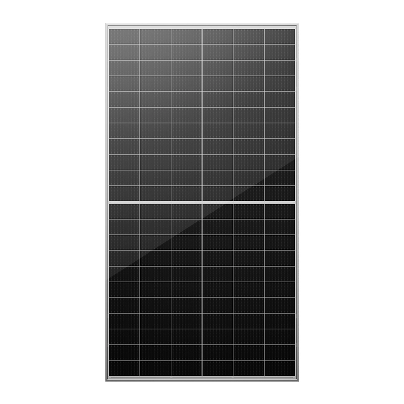
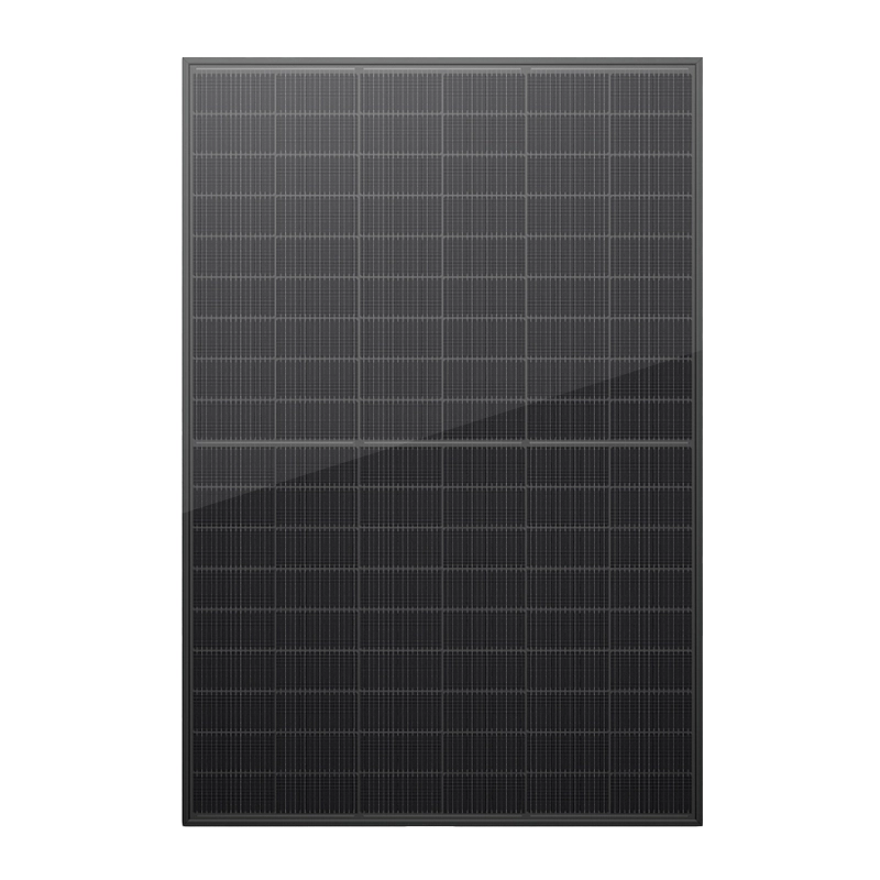
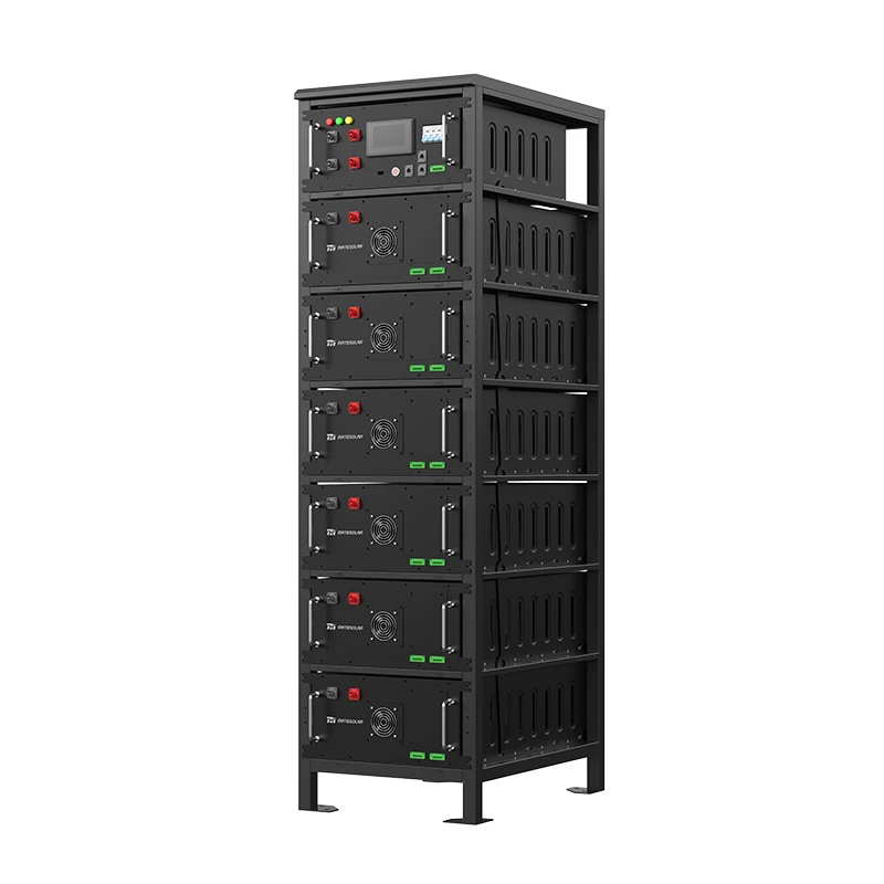
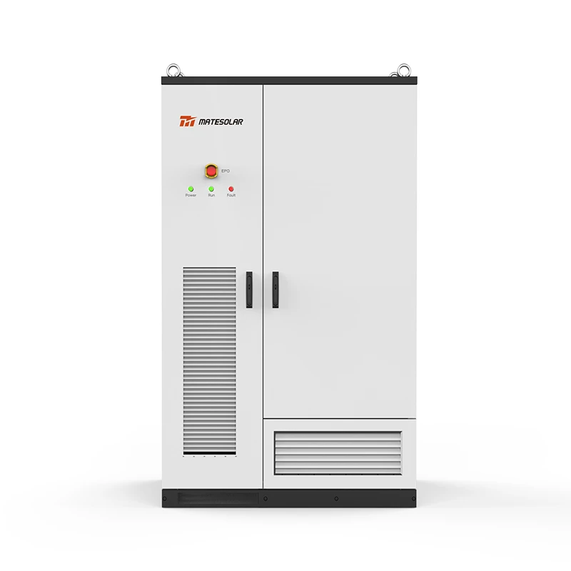
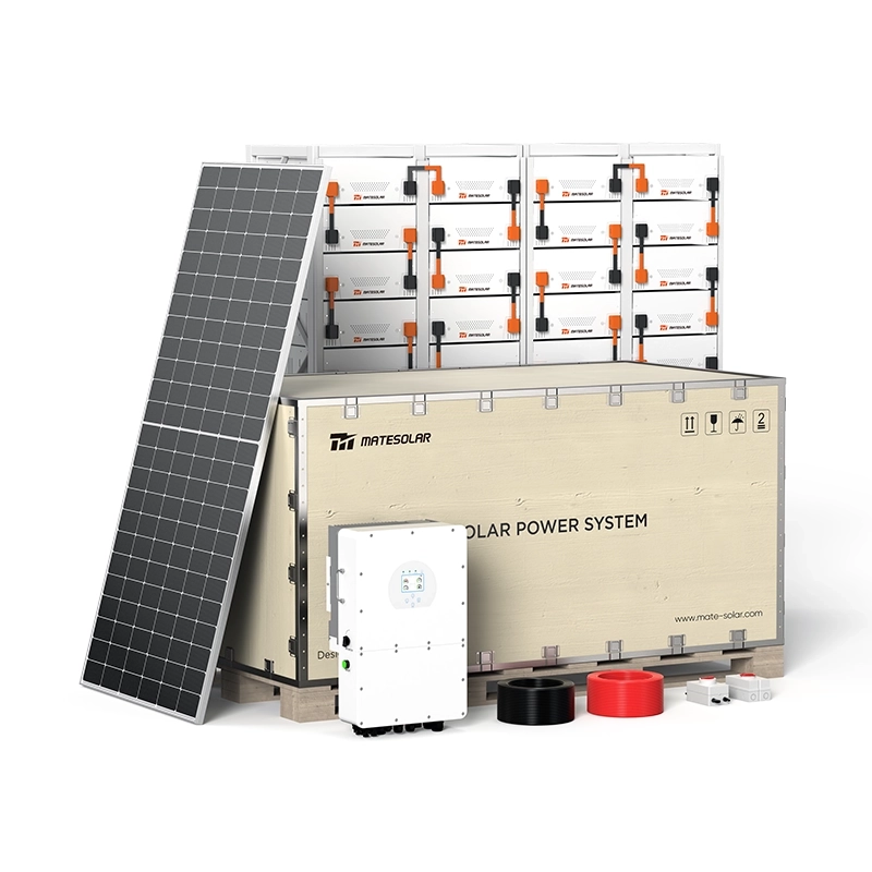
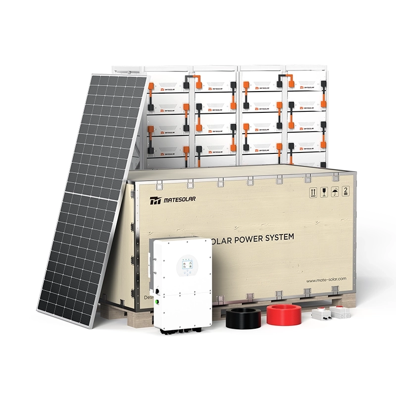
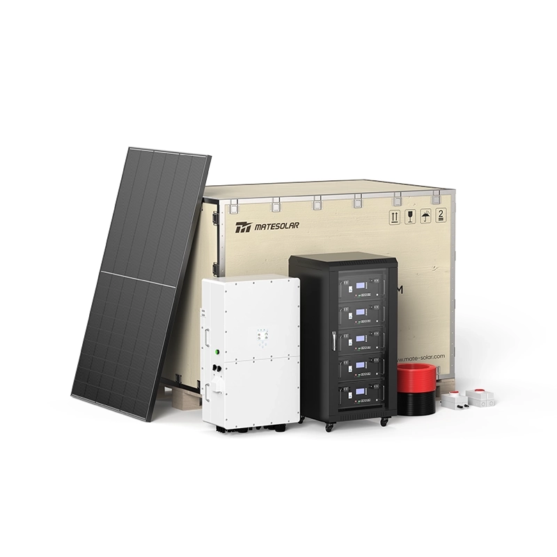
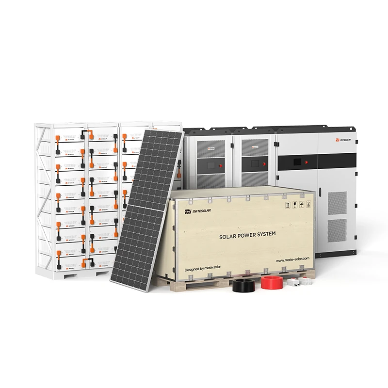
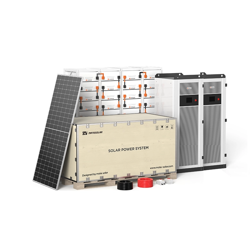
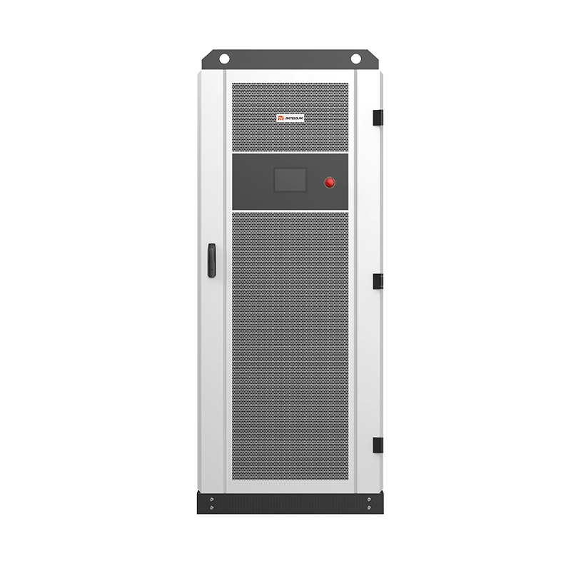
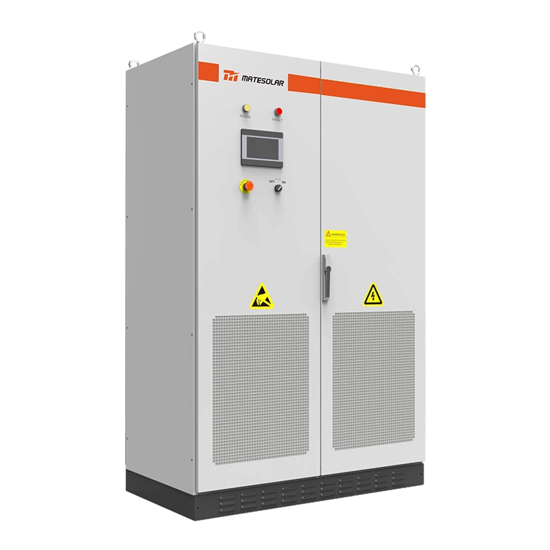
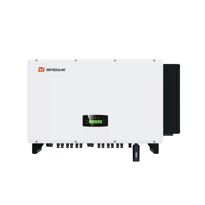
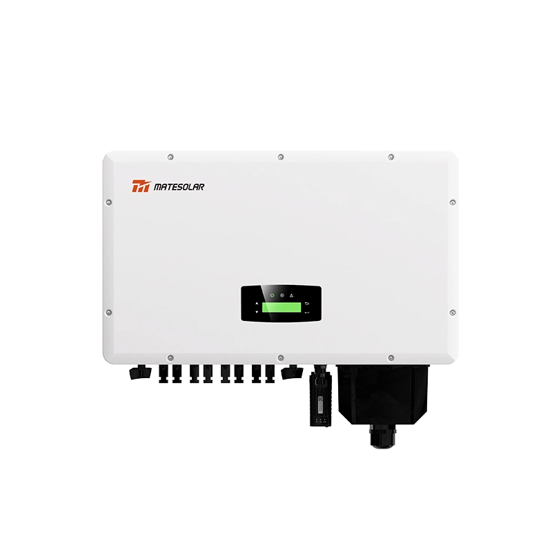
Kommerzielles 500kW Hybrid-Solarsystem
Für große kommerzielle und industrielle Anlagen, die umfassende Energieunabhängigkeit anstreben, kombiniert das Commercial 500kW Hybrid Solar System hocheffiziente PV-Erzeugung mit integrierter Batteriespeicherung. Diese schlüsselfertige Lösung ist für nordamerikanische C&I-Anwendungen konzipiert und liefert:
- 500 kW AC Ausgangsleistung
- Integrierter Hybridwechselrichter mit nahtloser Netz-/Inselumschaltung
- Intelligentes Energiemanagement mit optimierter Spitzenlastabrechnung
- UL9540A-konforme Sicherheitssysteme
- Fernüberwachung und -steuerung über Cloud-Plattform
Um mehr darüber zu erfahren, wie dieses System die Energiewirtschaft Ihrer Anlage verändern kann, besuchen Sie die Produktseite unter:
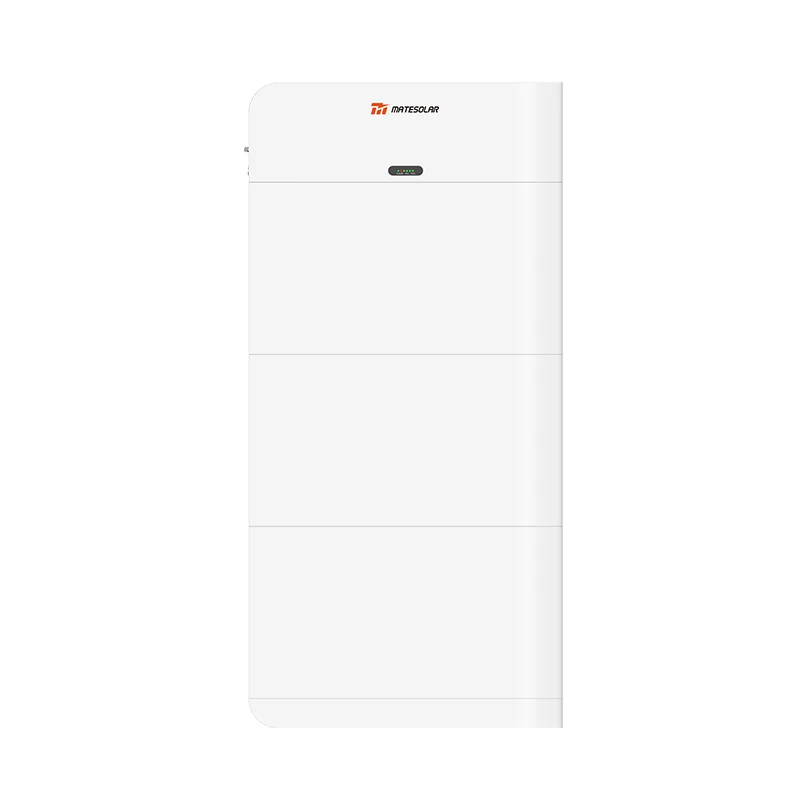
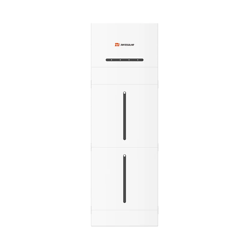
125kW/261kWh Flüssigkeitsgekühlter Outdoor-Schrank ESS
Der 125kW/261kWh flüssigkeitsgekühlte Outdoor-Schrank repräsentiert den neuesten Stand der Technik im Bereich C&I-Energiespeicherung. Diese All-in-One-Lösung bietet:
- Kapazität 261kWh DC-Seite, 125kW AC-Nennleistung
- Kühlung Fortschrittliche Flüssigkeitskühlung mit einer Zelltemperaturgenauigkeit von ±2°C
- Fußabdruck: Kompaktes 1,47 m² Design
- Batterie: 314Ah LFP-Zellen mit über 8.000 Zyklen Lebensdauer
- Sicherheit Konform mit UL9540A sechste Auflage
- Modularität: Erweiterbar durch Parallelschaltung
Detaillierte Spezifikationen und Fallstudien sind verfügbar unter:
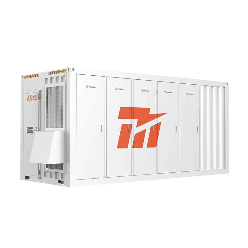
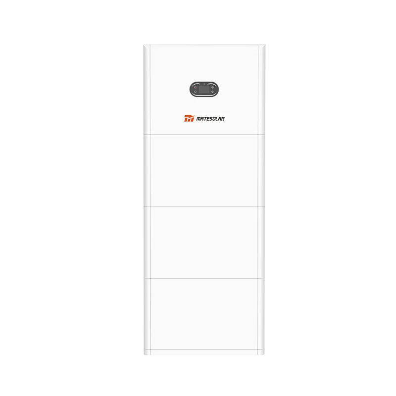
40 Fuß 1 MWh–2 MWh luftgekühlter Container-Energiespeicher
Für größere Industrie- und Gewerbeanwendungen sowie für kleinere Versorgungsanwendungen bietet die containerisierte 40-Fuß-ESS eine flexible Kapazität von 1 MWh bis 2 MWh:
- Kapazitätsbereich 1 MWh bis 2 MWh
- Kühlung Intelligente Luftkühlung mit Langzeitstabilität
- Bereitstellung Vormontiert und werkseitig getestet für eine schnelle Installation vor Ort
- Modularität: Unterstützt nahtlose Energie- und Stromerweiterungen
- Anwendung: Gewerblich, industriell und kleinmaßstäblich für Versorgungsunternehmen
Erkunden Sie diese Lösung weiter unter:
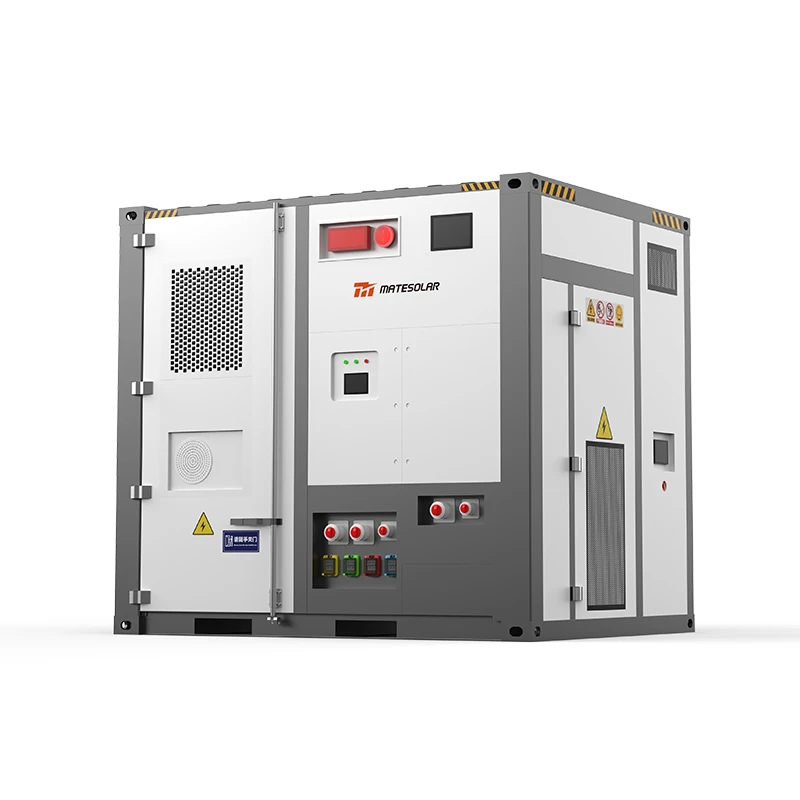
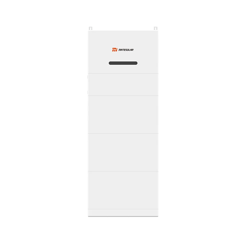
20 Fuß 3 MWh–5 MWh Flüssigkühlungscontainer-Energiespeichersystem
Für großtechnische Anlagen und große gewerblich-industrielle Anwendungen, die maximale Energiedichte erfordern, liefert der flüssigkeitsgekühlte 20-Fuß-Container 3 MWh bis 5 MWh auf kompakter Fläche:
- Kapazitätsbereich 3 MWh bis 5 MWh
- Zellenoptionen: 280Ah und 314Ah LFP-Zellen
- Kühlung Fortschrittliche Flüssigkeitskühlung für überragendes Wärmemanagement
- Energiedichte: Branchenführend MWh pro Quadratfuß
- Anwendung: Großspeicher im Versorgungsmaßstab, große Industrie, Netzbezogene Dienstleistungen
Technische Daten und Projekt Referenzen finden Sie unter:
Teil IV: Häufig gestellte Fragen
FAQ 1: Was ist die tatsächliche Lebensdauer eines Lithium-Batteriespeichersystems?
Antwort: Die Lebensdauer hängt von den Betriebsbedingungen ab. Unter Standardbedingungen (25 °C, 80% DOD, 0,5C) erreichen LFP-Systeme in der Regel 8.000–10.000 Zyklen. Bei einem Zyklus pro Tag entspricht dies einer Lebensdauer von 22–27 Jahren. Die kalendarische Alterung (zeitbedingte Leistungsminderung) begrenzt die Nutzungsdauer jedoch in der Regel auf 10–15 Jahre, unabhängig von der Anzahl der Zyklen.
FAQ 2: Wie überprüfe ich die Angaben eines Herstellers zur Lebensdauer im Zyklusbetrieb?
Antwort: Erfordern
1. Vollständige Offenlegung der Testbedingungen (Temperatur, DOD, C-Rate, SOH-Definition)
2. Prüfberichte von Drittanbietern von anerkannten Laboren
3. Garantiebedingungen, die mit den Lebensdauerangaben übereinstimmen
4. Referenzen von bestehenden Installationen mit ähnlichen Betriebsprofilen
FAQ 3: Was ist der Unterschied zwischen AC-gekoppelten und DC-gekoppelten Speichern?
Antwort: In AC-gekoppelten Systemen verbindet sich der Speicher über einen eigenen Wechselrichter mit dem AC-Bus. In DC-gekoppelten Systemen verbindet sich der Speicher mit dem DC-Bus eines Solarwechselrichters. AC-gekoppelte Systeme sind flexibler (können zu bestehenden PV-Anlagen hinzugefügt werden) und einfacher zu entwerfen. DC-gekoppelte Systeme erzielen eine höhere Round-Trip-Effizienz (weniger Umwandlungen), sind aber komplexer und werden typischerweise nur in Neuanlagen eingesetzt.
FAQ 4: Wie viel Platz benötige ich für ein C&I-Speichersystem?
Antwort: Der Platzbedarf hat sich mit Flüssigkeitskühlung und Hochleistungszellen erheblich verringert. Ein 261-kWh-Schrank benötigt etwa 1,5 m². Ein 1-MWh-Container-System benötigt etwa 25 m² (einschließlich Freiraum). Beachten Sie immer die örtlichen Brandschutzbestimmungen, die zusätzliche Abstände zwischen den Einheiten erfordern können.
FAQ 5: Kann ich Speicher ohne technischen Support vor Ort installieren?
Antwort: Ja, vorausgesetzt:
- Das System ist vormontiert und werkseitig getestet (Plug-and-Play-Design)
- Die Installation folgt der detaillierten Dokumentation
- Ferninbetriebnahme und Fehlerbehebung sind verfügbar
- Hardwareprobleme werden durch Ersatzteile oder den Austausch von Geräten behoben
- Softwareprobleme werden über Fernwartungsdiagnosen und -updates behoben.
Dieses Modell – werkseitige Vormontage, Fernunterstützung und Ersatz auf Komponentenebene – wird für C&I-Speichersysteme zunehmend zum Standard und reduziert den Bedarf an technischem Personal vor Ort.
FAQ 6: Was passiert, wenn eine Komponente ausfällt?
Antwort: Unter modernen Liefervereinbarungen:
- Hardwareausfälle werden durch Ersatzteile behoben, die zum Standort versendet werden, mit detaillierten Installationsanleitungen.
- Schwerwiegende Ausfälle können zum Austausch der Einheit führen
- Softwareprobleme werden über Fernsupport gelöst
- Für große Projekte im Versorgungsmaßstab kann technischer Support vor Ort für Inbetriebnahme und Fehlersuche arrangiert werden.
FAQ 7: Wie interagiert die Speicherung mit bestehender Solar-PV?
Antwort: Speicher können durch AC-Kopplung (Anschluss an die AC-Schiene) zu bestehenden PV-Anlagen hinzugefügt werden. Das EMS koordiniert die PV-Erzeugung, den Speicherbetrieb und die Anlagenlast, um wirtschaftliche Ergebnisse zu optimieren. Wichtige Überlegungen sind:
- Der Anti-Reverse-Leistungsflussschutz muss den PV-Export berücksichtigen
- Die Messung muss PV, Speicher und Last separat erfassen
- Die ökonomische Optimierung muss sowohl die Einnahmequellen aus PV als auch aus Speichern berücksichtigen
FAQ 8: Wie hoch ist die Amortisationszeit für C&I-Speicher im Jahr 2026?
Antwort: Amortisationszeiten variieren je nach Markt, liegen aber in den USA typischerweise zwischen 3 und 7 Jahren für C&I-Speicherlösungen. Wichtige Treiber sind:
- Lokale Stromtarife und Grundgebühren
- Verfügbarkeit von Anreizen (ITC, staatliche Programme)
- Systemkosten und Leistung
- Auslastungsgrade (Zyklen pro Tag)
Angesichts der derzeitigen ITC-Vorteile (30% für eigenständige Speichersysteme) und typischer Senkungen der Leistungsgebühren um 20–50% amortisieren sich viele C&I-Projekte innerhalb von 4–5 Jahren.
FAQ 9: Was ist der Unterschied zwischen kW und kWh bei Speichern?
Antwort: kW (Kilowatt) misst Leistung – die Rate, mit der Energie geliefert oder verbraucht wird. kWh (Kilowattstunden) misst Energie – die gespeicherte Gesamtmenge. Ein 125kW/261kWh-System kann 125kW Leistung für etwa 2 Stunden liefern (261 ÷ 125 ≈ 2,1 Stunden). Das Verständnis dieses Unterschieds ist entscheidend für die Dimensionierung von Speichern für spezifische Anwendungen.
FAQ 10: Wie bemessere ich ein Speichersystem für meine Einrichtung?
Antwort: Die richtige Dimensionierung erfordert:
1. Analyse der Belastung: 12+ Monate an Lastdaten im 15-Minuten-Intervall
2. Ratenanalyse Verständnis der Tarifstruktur (Leistungsentgelte, zeitabhängige Tarife)
3. Anwendungsdefinition: Spitzenlastabdeckung, Arbitrage, Notstromversorgung oder Kombination
4. Finanzmodellierung Optimierung der Kapazität im Verhältnis zu Kosten und Ertrag
5. Standortbewertung Weltraum, elektrische Infrastruktur, Genehmigungsbeschränkungen
Teil V: Technische Referenztabellen
Tabelle 1: Lithium-Batterie-Chemie-Vergleich (2026)
| Parameter | LFP | NMC | LTO | Natriumion |
| Energiedichte (Wh/kg) | 160–190 | 200–260 | 80–100 | 120–160 |
| Zykluslebensdauer (80% SOH) | 6,000–10,000 | 2,000–4,000 | 10,000–20,000 | 4,000–6,000 |
| Thermisches Durchgehen Temperatur | >500°C | ~200°C | >500°C | >500°C |
| Kosten ($/kWh) | $80–110 | $100–140 | $200–300 | $70–100 |
| Marktanteil (2026) | ~85% | ~8% | ~2% | ~5% |
Tabelle 2: Richtlinien für die Dimensionierung von C&I-Speichern
| Art der Einrichtung | Typische Last | Empfohlene Lagerung | Hauptanwendung |
| Einzelhandel (10.000 ft²) | 50–150 kW | 100–300 kWh | Rasierspitzen |
| Bürogebäude (4.645 m²) | 200–500 kW | 400–1.000 kWh | Lastspitzenkappung + Arbitrage |
| Fertigung (Klein) | 300–800 kW | 600–1.600 kWh | Nachfragemanagement |
| Industrielle Fertigung (Groß) | 1–5 MW | 2–10 MWh | Bedarfsmanagement + Backup |
| Rechenzentrum | 500 kW–5 MW | 1–10 MWh | Backup + Stromqualität |
Tabelle 3: Zusammenfassung der US-Speicherförderprogramme 2026
| Anreiz | Bewerten | Berechtigung | Status (2026) |
| ITC (Standalone-Speicher) | 30% | Alle Speicher | Aktiv |
| ITC (Solar+Speicher) | 30% | Kollokiert mit Solar | Aktiv |
| Abschnitt 45X | Variable | Inländische Produktion | Aktiv |
| Kalifornien SGIP | Bis zu $0,25/Wh | C&I Speicherung | Aktiv |
| NY-Sonne | Variable | NY Gewerbelager | Aktiv |
| MA SMART | Variable | MA-Speicher | Aktiv |
Tabelle 4: Leitfaden zur Auswahl des Kommunikationsprotokolls
| Protokoll | Geschwindigkeit | Anmeldung | Wann verwenden |
| IEC 60870-5-104 | Sekunden | Netzdispatch | Immer (Pflicht für Netzanschluss) |
| IEC 61850 GOOSE | Millisekunden | Schnellsteuerung | Frequenzregelung, netzbildend |
| MODBUS TCP | Mäßig | Gerätekommunikation | Standard für PCS, BMS, Zähler |
| CAN | Schnell | Modulkommunikation | Batteriemodul BMS |
| 485/RS-485 | Langsam | Sensoren | Umweltüberwachung |
Tabelle 5: Systemarchitekturvergleich
| Merkmal | Zentralisiert | String/Modular | Hybrid |
| PCS pro Cluster | 1:N | 1:1 | wenige |
| Wirkungsgrad | Höchste | Mäßig | Hoch |
| Verlässlichkeit | Niedrigste | Höchste | Hoch |
| Kosten/kW | Niedrigste | Höchste | Mäßig |
| Skalierbarkeit | Begrenzt | Ausgezeichnet | Gut |
| Beste Anwendung | Anlagen im Versorgungsmaßstab | C&I, Mikronetz | Große C&I |
Tabelle 6: Kennzahlen zur Leistung des Wärmemanagements (2026)
| Methode der Kühlung | Temperaturgleichmäßigkeit | Parasitär belasten | Wartung | Kostenzuschlag |
| Luftkühlung | ±5°C | 2–3% | Niedrig | Basis |
| Kühlplatte Flüssigkeit | ±2°C | 3–5% | Mäßig | +15–25% |
| Tauchflüssigkeit | ±1°C | 4–6% | Hoch | +40–60% |
Tabelle 7: Wichtige regulatorische Meilensteine 2026
| Regulierung / Standard | Wirksamkeitsdatum | Auswirkungen |
| GB/T 51048-2025 | 1. April 2026 | Vorschriften zur Prüfung der thermischen Durchgehensicherheit |
| UL9540A Sechste Ausgabe | 13. März 2026 | Erfordert groß angelegte Brandprüfung (LSFT) |
| Standards für netzbildende Umrichter (Entwurf) | H2 2026 | Definiert Überstrom, Dämpfung und Schaltanforderungen |
| GB/T 43526-2023 (bereits in Kraft) | 2023 | Technische Spezifikationen der ESS auf der Benutzerseite |
Teil VI: Marktausblick 2026 und strategische Implikationen
Der KI-gesteuerte Nachfrageschub
Die Integration von künstlicher Intelligenz und Recheninfrastruktur in Stromsysteme – die "Synergie von Rechenleistung und Strom" – stellt in den kommenden zehn Jahren einen der bedeutendsten Nachfragetreiber für Energiespeicherung dar. Rechenzentren, die sowohl einen massiven Stromverbrauch als auch eine extrem zuverlässige Versorgung benötigen, wenden sich zunehmend der Speicherung zu für:
- Notstrom bei Netzstörungen
- Verbesserung der Energiequalität
- Teilnahme an Lastmanagementprogrammen
- Integration mit dezentraler erneuerbarer Energieerzeugung
Die Nationale Energieverwaltung prognostiziert ein jährliches Stromnachfragewachstum von rund 600 Milliarden kWh während des Zeitraums des "15. Fünfjahresplans", das maßgeblich von der Nachfrage nach Computern und KI getrieben wird.
Der Rasterübergang
Mit zunehmender Verbreitung erneuerbarer Energien beschleunigt sich der Übergang von netzfolgenden zu netzbildenden Speichern. Bis 2026 wird die netzbildende Fähigkeit für viele netzgebundene Anwendungen von einem Alleinstellungsmerkmal zu einer Anforderung werden. Die anstehenden nationalen Standards für netzbildende Umrichter werden klare Leistungsanforderungen und Testmethoden festlegen.
Die Sicherheitsnotwendigkeit
Die sechste Auflage der UL9540A mit ihrer verpflichtenden Anforderung an Großbrandtests stellt einen Paradigmenwechsel in den Sicherheitsstandards für Energiespeicher dar. Projekte, die keine Verhinderung der Brandausbreitung auf Systemebene nachweisen können, werden regulatorischen Hürden, Versicherungs- und Finanzierungsschwierigkeiten gegenüberstehen. Dies ist besonders kritisch im nordamerikanischen Markt, wo die UL9540A-Zertifizierung zu einer de-facto-Anforderung für die Finanzierbarkeit von Projekten geworden ist.
Die Profitabilitätsgleichung
Der Übergang von einer politikgetriebenen zu einer marktorientierten Bereitstellung bedeutet, dass Speicherprojekte nun wirtschaftlich eigenständig sein müssen. Erfolgreiche Projekte im Jahr 2026 und darüber hinaus werden:
1. Optimierung für mehrere Einnahmequellen (Arbitrage, Reduzierung von Spitzenlastgebühren, Zusatzdienstleistungen)
2. Erreichen einer RTE auf Systemebene von über 88%
3. Hohe Verfügbarkeit gewährleisten (>98%)
4. Nachweis von bankfähigen Sicherheitszertifizierungen
5. Intelligentes EMS für Echtzeitoptimierung nutzen
Regionaler Fokus: Nord- und Mittelamerika
Für den nordamerikanischen Markt schaffen die ITC-Anreize, hohe Stromkosten und die zunehmende Instabilität des Stromnetzes ein überzeugendes Umfeld für den Einsatz von Energiespeichern in Industrie- und Gewerbeanlagen. Allein der US-Markt wird voraussichtlich bis 2026 70 GWh installieren, wobei Anwendungen in Industrie und Gewerbe einen wachsenden Anteil ausmachen werden. Zentralamerikanische Märkte (ohne Kuba und Mexiko) zeigen ebenfalls starkes Wachstum, angetrieben durch steigende industrielle Nachfrage und verbesserte regulatorische Rahmenbedingungen.
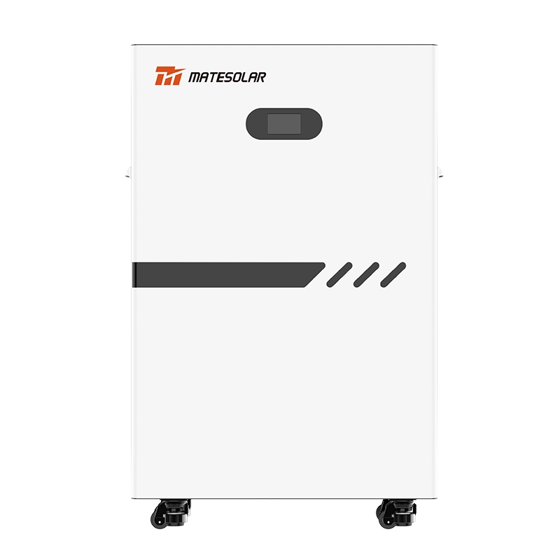
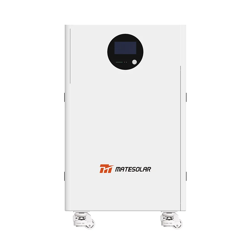
Das Produktportfolio von MateSolar ist speziell auf die Anforderungen dieser Märkte zugeschnitten, mit der Zertifizierung UL9540A sechste Ausgabe, 60 Hz / 480V AC-Ausgangskompatibilität und einer Infrastruktur für Fernunterstützung, die keine lokalen Installationsteams erfordert. Unsere Systeme werden vollständig vormontiert und werkseitig getestet geliefert und erfordern vor Ort lediglich Tiefbauarbeiten und elektrische Anschlüsse. Hardwareprobleme werden durch Ersatzteile mit detaillierten Installationsanleitungen oder durch den Austausch von Einheiten bei größeren Ausfällen behoben. Softwareprobleme werden über Ferndiagnose und Over-the-Air-Updates gelöst. Für große Projekte im Versorgungsmaßstab können wir auf Anfrage technisches Personal zur Inbetriebnahme und Fehlerbehebung vor Ort entsenden.
Schlussfolgerung: Meisterschaft im Zeitalter der Speicherung
Die Energiespeicherbranche ist in die Reifephase eingetreten. Die Ära der einfachen, politisch motivierten Einführung ist vorbei; die Ära der marktgetriebenen Leistung ist angebrochen. Für Fachleute in diesem Bereich ist die Beherrschung der technischen, operativen und kommerziellen Dimensionen der Lithium-Batteriespeicherung nicht mehr optional – sie ist die Grundlage für professionelle Glaubwürdigkeit und kommerziellen Erfolg.
Die 18 Wissensgebiete, die in diesem Kompendium behandelt werden, stellen das wesentliche Werkzeug für die Navigation in der Speicherlandschaft von 2026 dar:
- Technische Grundlagen (Zyklenlebensdauer, RTE, Balancing, Kühlung)
- Sicherheit und Zertifizierung (UL9540A, Brandschutz)
- Anwendungswissen (Energie vs. Leistungszellen, netzbildend)
- Systemdesign (Architekturauswahl, Spannungsauswahl, Verpolungsschutz)
- Integration (Solar+Speicher, Kommunikation)
- Wirtschaft (Nachfragemanagement, Umsatzoptimierung)
Diejenigen, die diese Bereiche beherrschen, werden in der Lage sein, eine Branche anzuführen, deren weltweiter Markt bis 2030 voraussichtlich Billionen US-Dollar erreichen wird. Diejenigen, die dies nicht tun, werden in einem Sektor, der immer höhere technische und kommerzielle Kompetenzen erfordert, zunehmend marginalisiert werden.
Dieses Kompendium wurde am 7. Juli 2026 erstellt und spiegelt die aktuellsten Marktdaten, technischen Standards und regulatorischen Entwicklungen wider, die zum Zeitpunkt der Veröffentlichung verfügbar waren. Die Energiespeicherbranche entwickelt sich rasant; die Leser werden ermutigt, spezifische technische Spezifikationen und regulatorische Anforderungen für ihre jeweiligen Anwendungen und Gerichtsbarkeiten zu überprüfen.
Über MateSolar
MateSolar ist ein führender Anbieter von Komplettlösungen für Photovoltaik und Energiespeicherung, der umfassende Solar-Plus-Speichersysteme für gewerbliche, industrielle und netzseitige Anwendungen liefert. Mit einem Produktportfolio, das von flüssigkeitsgekühlten Outdoor-Schränken mit 125 kW/261 kWh bis hin zu 5 MWh-Container-ESS-Plattformen reicht, kombiniert MateSolar fortschrittliche LFP-Batterietechnologie, intelligentes Energiemanagement und bankfähige Sicherheitszertifizierungen (konform mit UL9540A sechster Ausgabe), um schlüsselfertige Lösungen zu liefern, die Energieeinsparungen und Betriebszuverlässigkeit maximieren.
Unser Engagement geht über die Hardwarelieferung hinaus: Wir bieten Unterstützung bei der Ferninbetriebnahme, Fehlerbehebung bei Software und Logistik für den Austausch von Komponenten bei Hardwareproblemen – so stellen wir sicher, dass unsere Kunden unabhängig von ihrem geografischen Standort erstklassigen Support erhalten. Für Großprojekte steht auf Anfrage technischer Support vor Ort für Inbetriebnahme und Fehlerbehebung zur Verfügung.
Partnern Sie mit MateSolar – wo Innovation auf Zuverlässigkeit in derrevolutionären Energiespeicherbranche trifft.